OVERFLOW DEVICE
The machine is NOT equipped with an overow device, because the volume of the recovery tank is greater than the capacity of the solution
tank. In extraordinary cases, there is a mechanical device (oat) under the recovery tank lid that, when the recovery tank is full, shuts o the
air to the vacuum motor intake to protect it; the sound of the suction motor will then be deeper. Empty the recovery tank (see “EMPTYING THE
RECOVERY TANK”).
At the end of the work, and before carrying out any type of maintenance, perform the following operations:
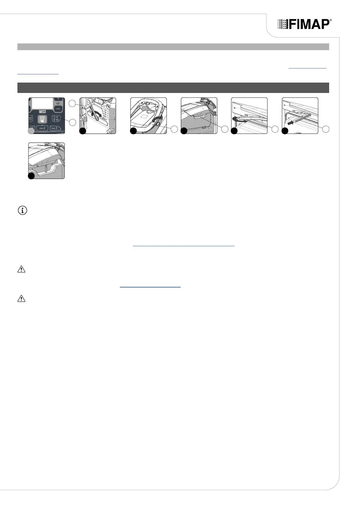
1. Lift the brush head body and press the “BRUSH HEAD CONTROL” button (1) on the control panel (Fig.1).
N.B.: As soon as the button (1) on the control panel is pressed, the green LED associated with this will switch o.
2. Raise the squeegee body o the oor by means of the lever (2) on the back of the machine (Fig.2).
3. Take the appliance to the dedicated dirty water drainage area.
4. Switch o the machine by turning the main switch (3) to "0", making a quarter turn of the key in the direction of the arrow (Fig.3). Remove
the key from the instrument panel.
5. Carry out all the procedures listed in the chapter “RECOMMENDED PERIODIC MAINTENANCE” indicated in the column “AT THE END OF
THE WORK”.
6. Take the machine to the designated machine storage place.
ATTENTION: Park the machine in an enclosed place, on a at surface; near the machine there must be no objects that could either
damage it, or be damaged through contact with it.
7. Secure the machine, see the section titled “SECURING THE MACHINE”.
ATTENTION: if the machine is left unused for more than one whole day, remove the brush from the brush head body, and the squeegee
body from the squeegee support.
8. Grip the handle (4) on the right-hand side of the recovery tank cover (Fig.4) and turn the tank cover as far as it will go.
9. Grip the prop (5) and turn it as far as it will go (Fig.5).
10. Block the rotation of the prop (5) by pushing it towards the inside of the cover (Fig.6).
11. Grip the handle (4) and turn the recovery tank cover until the prop (5) is resting on the recovery tank (Fig.7).
AT THE END OF THE WORK
25
7
2
2
3 4 5 6
3 4 5 5
1
1