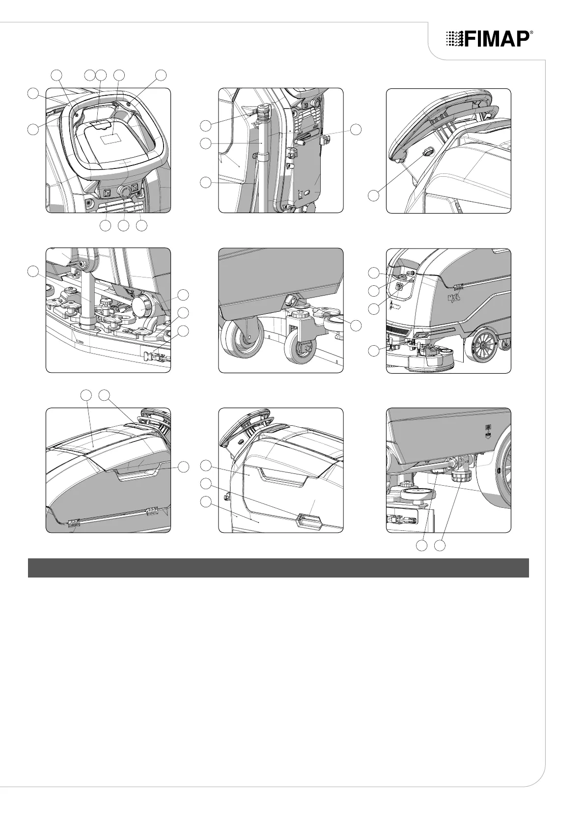
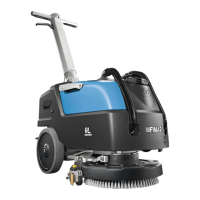
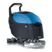
MAIN MACHINE COMPONENTS
The machine's main components are the following:
1. Dead man's lever.
2. Control handlebars.
3. Eco Mode button.
4. Cover for FFM “FIMAP FLEET MANAGEMENT” SOS button
(Optional).
5. FFM “FIMAP FLEET MANAGEMENT” SOS button (Optional).
6. Control panel and control display.
7. Reverse control button.
8. FSS “FIMAP SOLUTION SAVER” control switch (optional) or FLR
“FIMAP LONG RANGE” control switch (optional).
9. Battery disconnect button.
10. “TANK CLEANING GUN” control switch (optional) or “LIQUID
VACUUM WAND” control switch (optional).
11. Support hook for recovery tank drainage tube.
12. Recovery tank drainage hose.
13. Solution tank level indicator.
14. Squeegee body control lever.
15. Main key switch.
16. Vacuum tube.
17. Solution tank drainage cap.
18. Squeegee body support.
19. Squeegee body.
20. Water ow adjustment tap.
21. Solution tank ller tube cap.
22. Cover cap for FFF “FIMAP FAST FILL” quick coupling kit
(optional).
23. Solution tank ller cap/measuring inlet.
24. Front headlights (optional).
25. Accessory compartment door.
26. Control handle for accessory compartment door.
27. Recovery tank cover lifting handle.
28. Recovery tank.
29. Recovery tank lifting handle.
30. Solution tank.
31. Electric brake control lever
32. Detergent solution lter.
3
20
18
17
16
19
30
27
25 26
28
29
24
23
22
21
2
73 654
1
10 9 8
13
11
12
14
15
31 32