EN
14
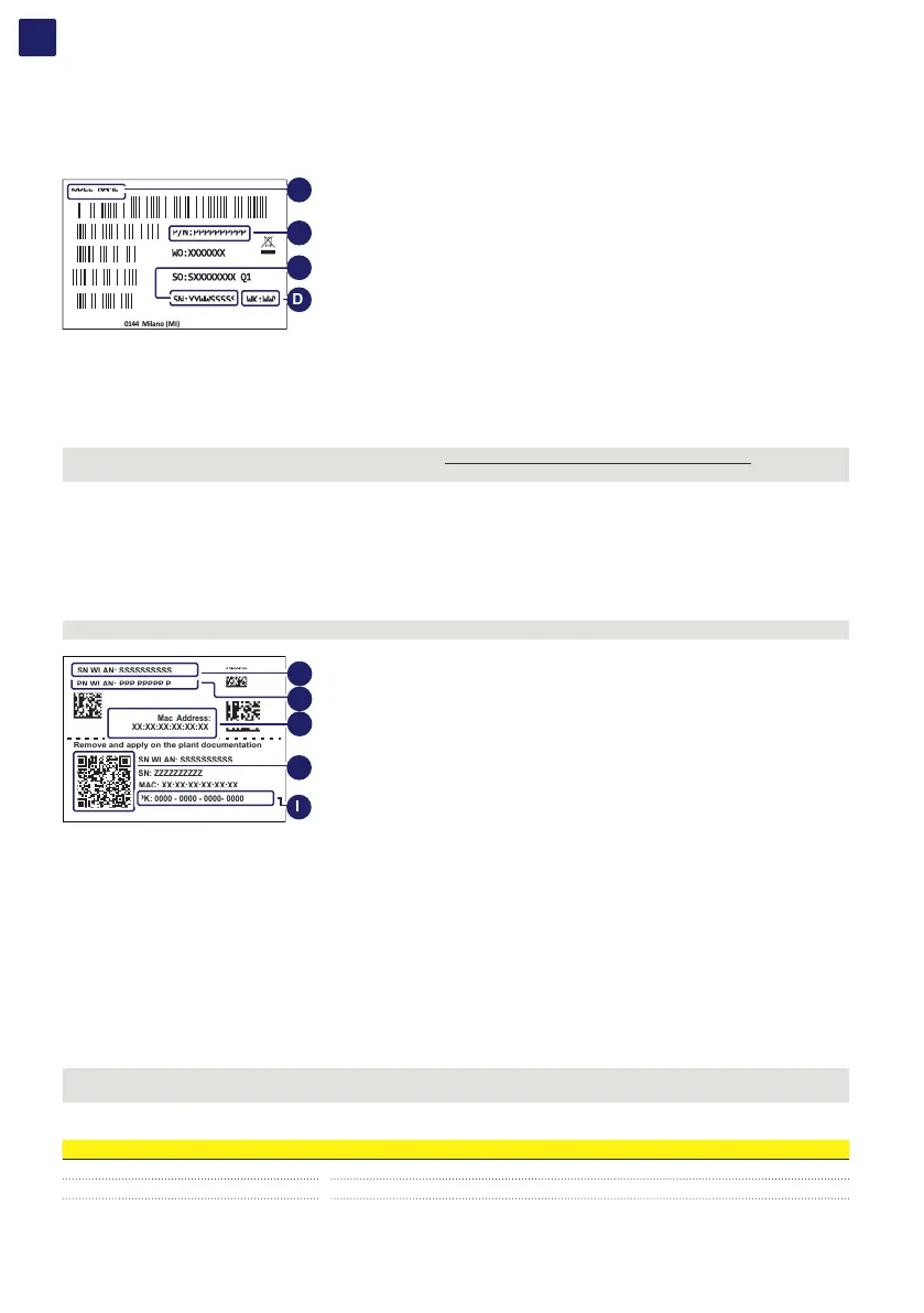
3.2.3 Inverter identification label
The identification label is an accessory label (applied on both the power module (01) and the wiring box (02)) which shows the information
necessary for the identification and characterization of the inverter.
Fimer S.p.A.
Via Tortona, 25 - I 20144 Milano (MI)
A
B
C
D
A. Power module/wiring box model
B. Inverter/wiring box Part Number
C. Inverter/wiring box Serial Number
D. Week/Year of manufacture
NOTE – D If the Admin Plus password is requested (referring to ““Registration website” and “Admin Plus token”” paragraph), the
information from identification label are mandatory.
3.2.4 Communication Identification label
The “communication identification label” (applied on the wiring box) is divided in two separate parts by a dashed line; take the bottom part
and apply it on the plant documentation.
NOTE – D It’s recommend to create a plant map and apply the “communication identification label” on it.
SN WLAN: SSSSSSSSSS
PN WLAN: PPP.PPPPP.P
Mac Address:
XX:XX:XX:XX:XX:XX
PK: 0000 - 0000 - 0000- 0000
SN WLAN: SSSSSSSSSS
SN: ZZZZZZZZZZ
Remove and apply on the plant documentation
MAC: XX:XX:XX:XX:XX:XX
F
G
H
J
I
F. WLAN embedded board Serial Number
G. WLAN embedded board Part Number
H. MAC address:
- To be used to obtain the SSID of the wireless access point created by the inverter: ABB-XX-XX-XX-XX-XX-XX (where “X” is a hex
digit of the MAC address).
- To be used to obtain the “Host Name”: http://ABB-XX-XX-XX-XX-XX-XX.local (where “X” is a hex digit of the MAC address).
I. Product Key:
To be used as wireless access point password, or to be used to access to the Web UI as username and password in case of lost
credentials, and to commission inverter using FIMER Installer for Solar Inverters.
J. QR Code:
To be used to commission inverter using FIMER Installer for Solar Inverters for claiming process.
3.3 Models and range of equipment
NOTE – D The choice of the inverter model must be made by a qualified technician who knows about the installation conditions, the
devices that will be installed in addition to the inverter and possible integration with an existing system.
The parts of equipment which make up the inverter are:
Power Module Model Description
PVS-100-TL-POWER MODULE Inverter section / power module with 100kW output power at 400Vac
PVS-120-TL-POWER MODULE Inverter section / power module with 120kW output power at 480Vac