EN
70
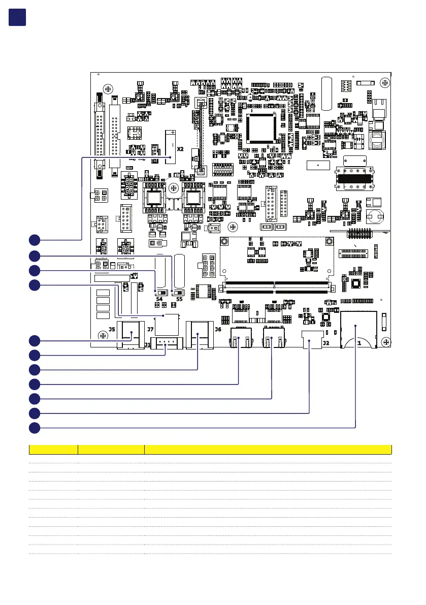
5.11 Connection of the communication and control signals
5.11.1 Communication and control board references
J2 X1
X2
S5S4
J7
J1
J5 J6
1
2
1
8
7
432
34
35
42
41
40
39
38
37
33
36
43
Terminal name Terminal reference Description
J5 33 Configurable relay connector (ALARM and AUX terminal block)
S4 34 RS485 Fimer service 120Ohm termination resistance selector switch (Fimer service only)
S5 35 RS-485 line 120Ohm termination resistance switch
J7 36 RS-485 connector (RJ45) (Fimer Service only) (*)
J1 37 Remote ON/OFF terminal block (*)
J6 38 RS-485 line terminal block
- 39 Ethernet connector 2 (RJ45)
- 40 Ethernet connector 1 (RJ45)
J2 41 USB connector
X1 42 SD card slot
X2 43 CR2032 Coin battery
(*) The RS-485 connector (RJ45) (Fimer Service only) (36) and the signal R1 on the Remote ON/OFF terminal block (37) are used to bring
the signals on the external connector RS-485&Rem.ON/OFF (Service only) (57).