34
B. FLOOR (DRAG CONVEYOR)/FEED ROLL
The fixed displacement hydraulic pump feeds hydraulic oil to a flow divider manifold and from the
flow divider manifold, the other 33% of the oil flow is routed to the floor motor through a dump
valve system. The floor dump valve system, located on the conveyor leg next to the control box,
is actually three valves in one manifold. There is a relief valve set at set at 1850 psi (12 755 kPa)
to protect the circuit, a 12 VDC normally open dump valve solenoid cartridge and a 12 VDC
proportional flow control valve.
Oil entering the manifold flows back to the reservoir tank until a DC current activates the solenoid
valve. When the solenoid valve is actuated, oil is then directed through the 12 VDC proportional
flow control valve to drive the floor feed roll and to start moving the drag chain conveyor. By
pressing the floor increase (FLOOR INC) button on the control box, voltage is increased on
the proportional flow control solenoid increasing the flow to the floor feed roll and drag chain
conveyor. To decrease the speed of the conveyor and feed roll, press the floor decrease
(FLOOR DEC) button which reduces the voltage to the solenoid causing it to minimize oil flow.
The floor drag chain conveyor is driven off of the feed roll hydraulic motor.
SUBSYSTEM 3: HYDRAULIC CONTROL SYSTEM
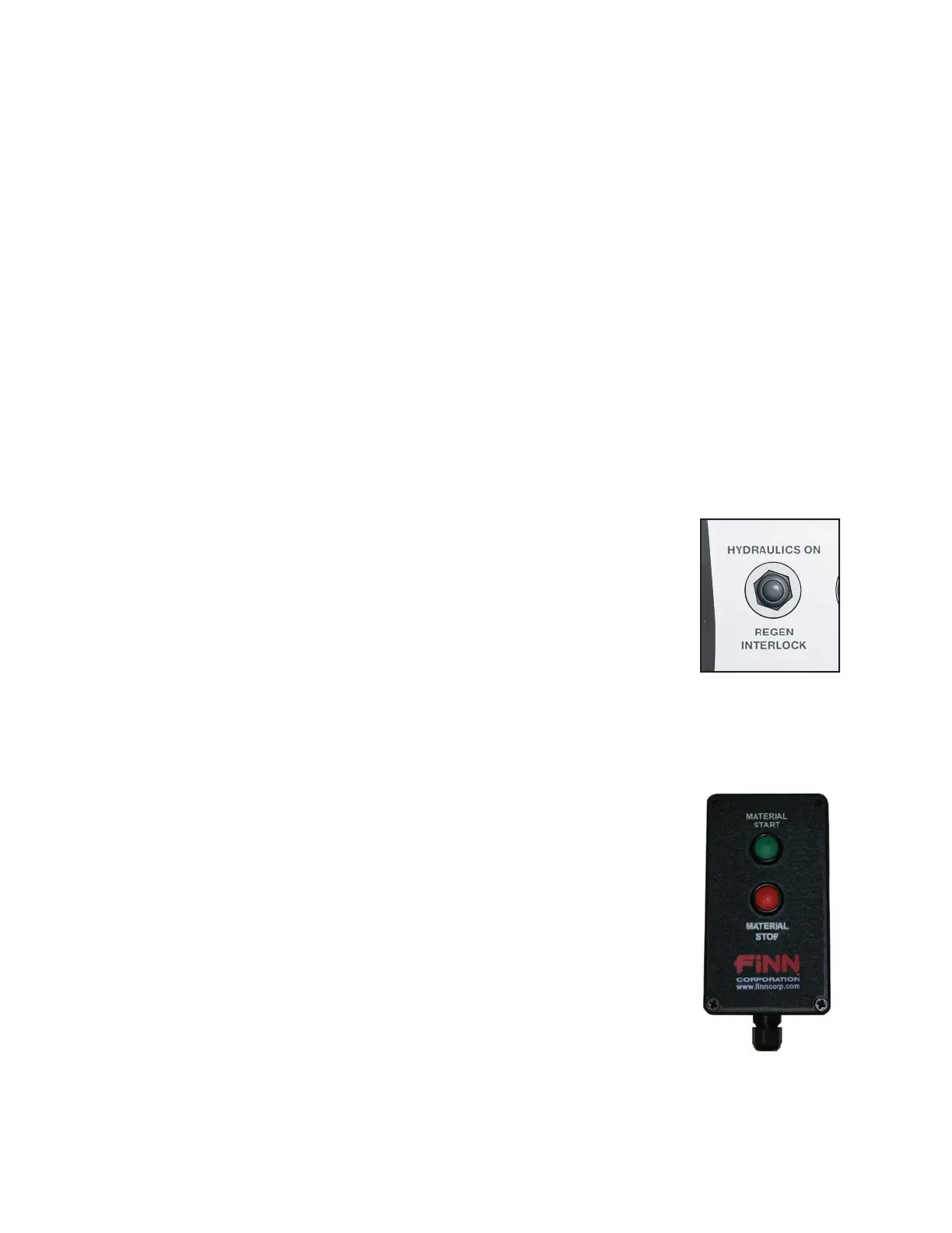
With the new Tier IV engines and the regeneration cycles that are required,
the hydraulic system now has a switch that allows the operator to effectively
turn ON/OFF the hydraulic circuit. When the toggle switch (located on the
control box) is in the REGEN INTERLOCK position, the hydraulic circuit is
closed (off), causing all of the oil flow to be routed back to the reservoir tank.
When the switch is flipped to the HYDRAULICS ON position, the circuit is
energized, allowing the operator to activate the various hydraulic circuits.
The hydraulic circuits are electronically controlled, allowing the operator the ability to control the
function of the rotary air valve as well as the floor feed roll and feed conveyor. Both circuits are
12 VDC and are powered from the engines electrical system. It is a self-contained system located
inside of the control box which controls all of the various solenoid valves in the system.
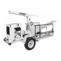
When the MATERIAL START button is pressed on the pendant, the rotary air
valve forward solenoid is energized, causing the vanes inside of the valve to
start turning. After the rotary air valve has started, the floor will start moving
after a 2-second delay.
NOTE: Control box Material Start / Stop and Floor Increase /
Decrease buttons will not work until initial start has
occurred at the hardwired Material Start pendant.
As material drops into the top of the rotary air valve, the hydraulic pressure
required to turn the rotary air valve varies. If the pressure reaches the
high-pressure relief valve threshold in the solenoid control valve, the oil is
channeled through the relief valve back to the hydraulic tank. In the forward
work line is a normally open pressure switch. When the pressure in the work
line exceeds the pressure-switch setting, the switch then closes and triggers the auto-reverse
sequence.