800027-A 27 06/05/2023
4.7.3 Discharge Piping and Fitting Specifications
All Firetrace ILP Units shall use copper tubing or equivalent, or the Firetrace discharge hoses for the FK-5-1-12 distribution system. The following
tubing and fittings shall be used. Refer to NFPA 2001, 2015 Edition - Section 4.2 for alternate discharge network options.
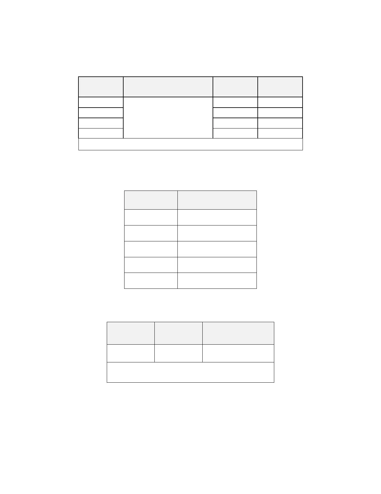
Table 33 – Discharge Piping Specifications
soft annealed copper
(AS B-280
*
, for air conditioning and
refrigeration service)
*
The use of AS B-280 soft annealed copper, as specified in this manual, complies with ASME B 31.1 requirements of
NFPA 2001.
Table 34 – Flexible Discharge Hose Specifications
Flexible Hose Part
Number
1/2 in Flexible Hose, 2 ft
1/2 in Flexible Hose, 4 ft
1/2 in Flexible Hose, 6 ft
1/2 in Flexible Hose, 8 ft
1/2 in Flexible Hose, 10 ft
Table 35 – Discharge Pipe Fitting Specifications
Minimum Pressure Rating
**
*
Use Parker Intru-Lok, Camozzi, or equivalent
**
Minimum pressure rating for use with Firetrace FK-5-1-12 ILP Units
4.7.4 Maximum Discharge Piping and Fitting Limitations
Table 36 – Discharge Piping Limitations, the below table shows the discharge piping and pipe fitting limitations for Firetrace Pre-Engineered FK-5-1-
12 ILP Automatic Suppression Units.