800027-A 28 06/05/2023
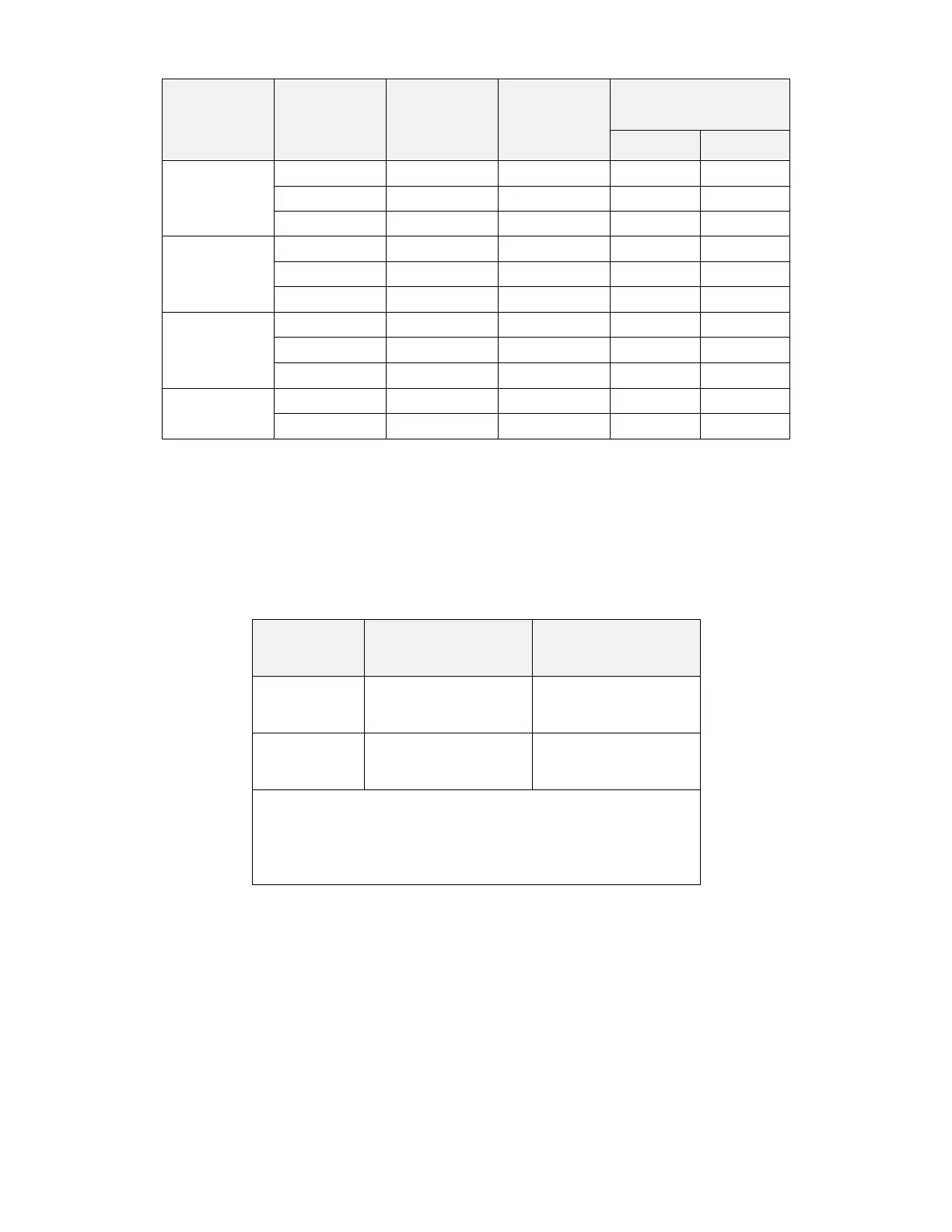
Table 36 – Discharge Piping Limitations
Nozzles per
Discharge Port
Maximum Length of
Discharge Piping per DP
4.7.5 Discharge Pipe Bends
Wherever possible, pipe bends should be used in lieu of 90° elbows. It is recommended that a pipe bender be used when forming the 90° bends.
Refer to Table 37 –Pipe Bend Radius and Equivalent Length when forming pipe bends, to minimize the chance of flattening the pipe.
Table 37 –Pipe Bend Radius and Equivalent Length
Minimum Bend Radius
*
to Pipe Centerline
Equivalent Length
**
for
90° Bend
***
*
The minimum bend radii were derived from Parker Industrial Tube Fittings Catalogue 4300,
dated March 1991.
**
The equivalent length is to be subtracted from the maximum length of piping as stated under
Table 36 – Discharge Piping Limitations.
***
90° pipe bends are not required to be subtracted from the maximum number of elbows stated
under Table 37 –Pipe Bend Radius and Equivalent Length.