800027-A 30 06/05/2023
5 INSTALLATION INSTRUCTIONS
This section provides installation instructions covering components and limitations described in Section 3 and Section 4 of this Manual.
All components should be installed to facilitate proper inspection, testing, recharging, and any other required service or maintenance as may be
necessary. Equipment must not be subjected to severe weather conditions or mechanical, chemical, or other damage which could render the
equipment inoperative. The equipment must be installed in accordance with instructions in this Manual and NFPA 2001.
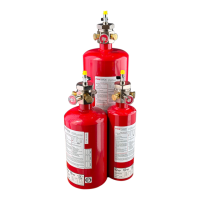
FK-5-1-12 cylinder/valve assemblies must be handled, installed, and serviced only by qualified and trained personnel in
accordance with the instruction contained in this manual, on the cylinder nameplate, and any other regulations and codes
that may apply. Failure to follow these instructions could result in property damage, severe injury, or death.
Pressurized (charged) cylinders are extremely hazardous and if not handled properly are capable of causing property damage,
bodily injury, or death. Always wear safety glasses and make sure the discharge plugs are properly in place before unit
installation, servicing, or other general handling.
5.1 FK-5-1-12 Cylinder/Valve and Bracket Assemblies
The FK-5-1-12 cylinders should be located as close as possible to the protected enclosure. In some cases the cylinder can be mounted inside the
protected enclosure. The assemblies shall be located in a readily accessible location to allow for ease of inspection, service, and maintenance. The
cylinders shall be located in an environment protected from the weather and where the temperature range is between 0°F to +130°F (-17.8°C to
+54.4°C).
The cylinder and bracket must be mounted in the vertical plane with the cylinder valve facing up and oriented so that the pressure gauge is facing out
and away from the mounting wall to facilitate visual inspection.
Mount the cylinder where it will not be subjected to accidental damage or movement. Suitable protection must be installed where necessary to prevent
damage or movement.
Make sure that the ball valve, located on the top of the cylinder valve, is maintained in the “OFF” position and the discharge
port safety plugs are kept in place until the system is secured in place and ready for connection of the discharge piping.
Failure to follow these instructions will result in actuation and discharge of the cylinder contents.
1. Securely mount the cylinder bracket to structural support using 2 or more mounting holes.
2. Position the cylinder in the bracket with the pressure gauge facing out. Secure the cylinder in place using the bracket straps or band
clamps.
5.2 Discharge Piping and Nozzles
1. Install the nozzle(s) following the guidelines and limitations described in Section 4.6.
2. Determine the routing of the discharge pipe and whether one (1) or two (2) discharge ports will be used following the guidelines and limitations
described in Section 4.6. If two (2) discharge ports are used, verify that the pipe length from each discharge port does not exceed a 10%
imbalance.
3. Remove one or two safety plugs from the valve discharge ports as required. Attach male connection fittings in discharge port(s) as applicable.
4. Install the discharge pipe and fittings between the cylinder and nozzle(s). Secure the pipe with the appropriate size pipe clamps as required.