800027-A 31 06/05/2023
5.3 Firetrace Detection Tubing
Location and spacing of the tubing is critical to the response time in the event of a fire. The tubing should be placed above the hazard areas being
protected. The Typical Tubing Placement diagram, located in Figure 16, provides general guidelines for placement of the detection tubing along with
the maximum spacing and height limitations. Depending on the configuration of specific hazards, the guidelines shown in the Typical Tubing Placement
diagram may, or may not, be applicable. The maximum height that is allowed between layers is 3.28 feet (1 m), the maximum distance between
passes is 21.12 inches (53.34 cm), and the maximum distance allowed from any wall to the tubing is 10.56 inches (26.82 cm). Refer to the Typical
Tubing Placement diagram in Figure 16 for further clarification. Tubing shall not be installed on any galvanic surfaces.
Do not kink, bend, or crush Firetrace tubing in order to prevent leakage which could result in accidental unit discharge. Do
not install tubing in a hazardous environment where the maximum ambient temperature exceeds 176°F (80°C). Maximum
length of detection tubing shall not exceed 120 Feet (36.58 m).
1. Secure the detection tubing using Mounting Tabs at 1.5 ft (0.46 m) intervals.
2. All FDT fittings at joints must be secured.
3. FDT must be secured within 6 in [15.24 cm] of all joints or fittings to prevent leakage due to bends near joints.
4. Use the appropriate rubber/plastic grommets when the detection tubing is routed through sharp holes, to prevent damage to the tubing.
5. When mounting to metal surfaces, rubber P-clips or a small piece of copper/rubber hosing is required to mount to the metal surface.
6. All FDT fittings and joints are to be inspected for leaks with a solution of liquid soap and water.
5.4 Detection Tubing Fittings and Accessories
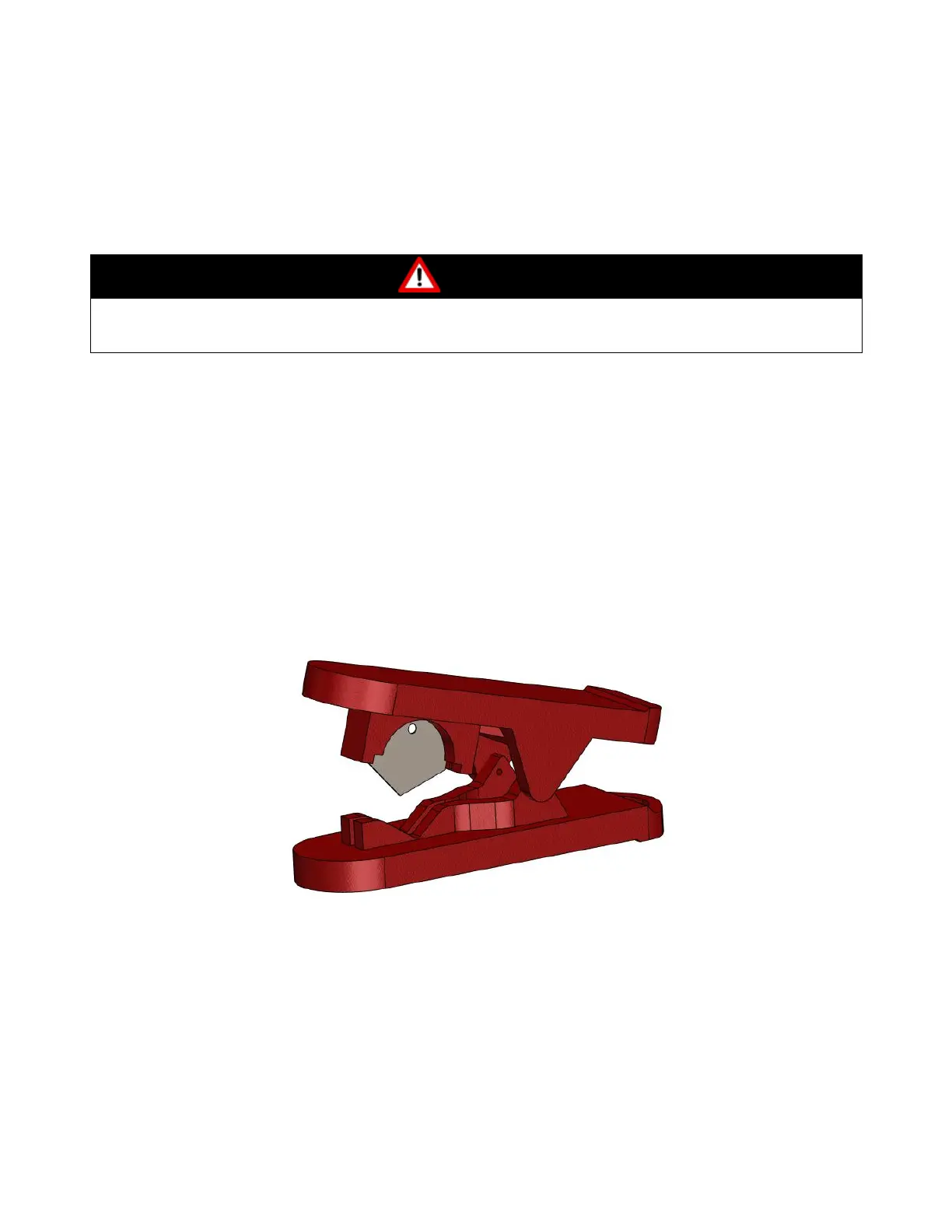
5.4.1 Firetrace Tubing Cutter (600210)
The Firetrace Tubing Cutter (P/N: 600210) is used to ensure that the Firetrace Detection Tubing (FDT) is cut with a square (perpendicular), clean
finish, free of debris.
Figure 17 – Firetrace Tubing Cutter 600210
5.4.2 Slip-On Fittings
All high-pressure slip-on fittings must be secured in the following manner:
1. Cut the tube end (using a Firetrace Detection Tube (FDT) cutter P/N: 600210), ensuring the cut is square, clean, and free from burrs. Verify
that no debris is left in the tube.
2. Thoroughly clean the tubing with a clean cloth (no cleaning agent) to a distance of at least 2 in [5.08 cm] from the cut end (removing all dirt,
grease, or grime). This will ensure a good seal inside the fitting.
3. Slide the tubing into the opening, until it butts up against the inner wall. Pull lightly on the tubing and the brass outer ring should move
outward slightly.
For a more comprehensive list of Slip-On Fittings, refer to Appendix A.