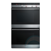
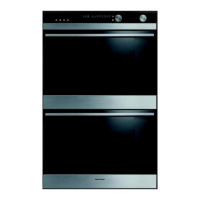
56
1. Ensure the product is isolated from the power
supply.
2. Remove the product from the joinery, refer to
section 8.1.
3. Remove the rear panel to gain access to the
element.
4. Remove the 2 ducting sections on left hand
side (1 on a single).
Single models and lower cavity elements:
5. Remove the wiring from the element and
remove the screw securing the element to
the support bracket.
6. Remove the 2 screws retaining the support
bracket to the rear chassis and bend the
bracket downwards enough to clear the
element.
7. Pull the element out from under the cavity.
Double model upper cavity
8. Remove the wiring to the lower vent fan.
9. Remove the lower vent fan by removing the 2
screws that secure it.
10. Remove the 2 screws retaining the cooling fan
cover.
11. Pull the fan cover with the cooling fan attached
upward to clear the locating tabs.
12. Allow the fan cover to drop down to clear the
element.
13. Remove the element retaining screw.
14. Pull the element out from under the oven cavity.
15. Reassemble in reverse order.
Note: When reinserting the element, use a wide flat
blade or similar object, to lift the cavity insulation
clear of the replacement element.
8.16 Removal of the Bake Element
1. Ensure the product is isolated from the power
supply.
2. Remove the oven doors and shelves.
3. Remove the fan shroud, refer 8.9.
4. Remove the 2 screws securing the element and
the 2 screws on the support frame on the
cavity roof.
5. Pull the tail of the element through the hole in
the cavity until the terminals are accessible.
Note: Tilt the element forward so that the element
terminals will clear the hole in the oven cavity.
6. Disconnect the wiring and connect the
replacement element.
7. Reassemble in reverse order.
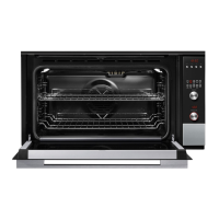
8.15 Removal of the Grill Element
element screws
support frame
screws
Ducting
Cooling Fan
Vent Fan
Element support
bracket
 Loading...