Instruction Manual
D102748X012
Principle of Operation
October 2014
96
The transducer board contains the Hall sensor, a temperature sensor to monitor the Hall sensor temperature, and an
EEPROM to store the coefficients associated with the Hall sensor. The terminal board contains the EMI filters, the loop
connection terminals, and the connections for the optional RTD used to measure process temperature.
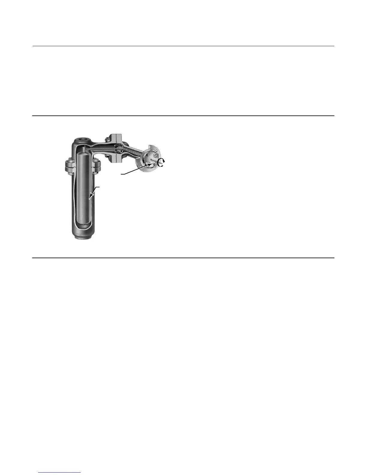
A level, density, or interface level change in the measured fluid causes a change in the displacer position (figure A‐5).
This change is transferred to the torque tube assembly. As the measured fluid changes, the torque tube assembly
rotates up to 4.4 degrees for a 249 sensor, varying the digital level controller output between 4 and 20 mA.
Figure A‐5. Typical Sensor Operation
TORQUE
TUBE
DISPLACER
249 SENSOR (SIDE VIEW)
W1389‐1
The rotary motion of the torque tube is transferred to the digital level controller lever assembly. The rotary motion
moves a magnet attached to the lever assembly, changing the magnetic field that is sensed by the Hall effect sensor.
The sensor converts the magnetic field signal to an electronic signal.
The microcontroller accepts the electronic signal, which is ambient‐temperature‐compensated and linearized. The
microcontroller can also actively compensate for changes in liquid specific gravity due to changes in process
temperature based on an input via HART protocol or via an optional RTD, if it is connected. The D/A output circuit
accepts the microcontroller output and provides a 4 to 20 mA current output signal.
During normal operation, when the input is between the lower and upper range values, the digital level controller
output signal ranges between 4 and 20 mA and is proportional to the input. See figure A‐6. If the input should exceed
the lower and upper range values, the output will continue to be proportional to the input until the output reaches
either 3.8 or 20.5 mA. At this time the output is considered saturated and will remain at this value until the input
returns to the normal operating range. However, should an alarm occur, the output is driven to either 3.7 or 22.5 mA,
depending upon the position of the alarm jumper.
 Loading...


