Instruction Manual
D102748X012
Principle of Operation
October 2014
97
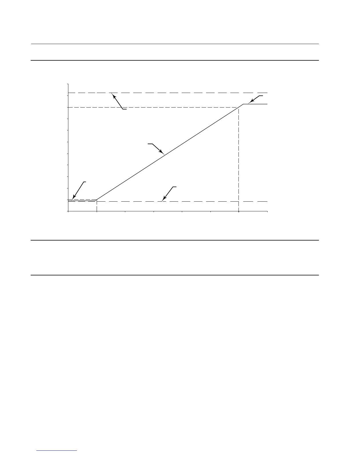
Figure A‐6. Digital Level Controller Analog Output Signal
2
4
6
8
10
12
14
16
18
20
22
24
-20% 0% 20% 40% 60% 80% 100% 120%
Output during Alarm with
Alarm Jumper in Hi Position
Output Saturated
(3.8 mA)
(22.5 mA)
Output during Alarm with
Alarm Jumper in Lo
Position
(3.7 mA)
Output Saturated
(20.5 mA)
Normal Operation
Output (mA)
PV Range
E0379
Note
The upper alarm value is compliant with NAMUR NE‐43, but the lower alarm value is not.
If using in a system with NAMUR NE‐43 compatibility, the high alarm value may be an appropriate choice.
Other circuits in the digital level controller provide reverse polarity protection, transient power surge protection, and
electromagnetic interference (EMI) protection.
 Loading...


