Instruction Manual
D103409X012
Field Communicator Menu Trees
May 2013
132
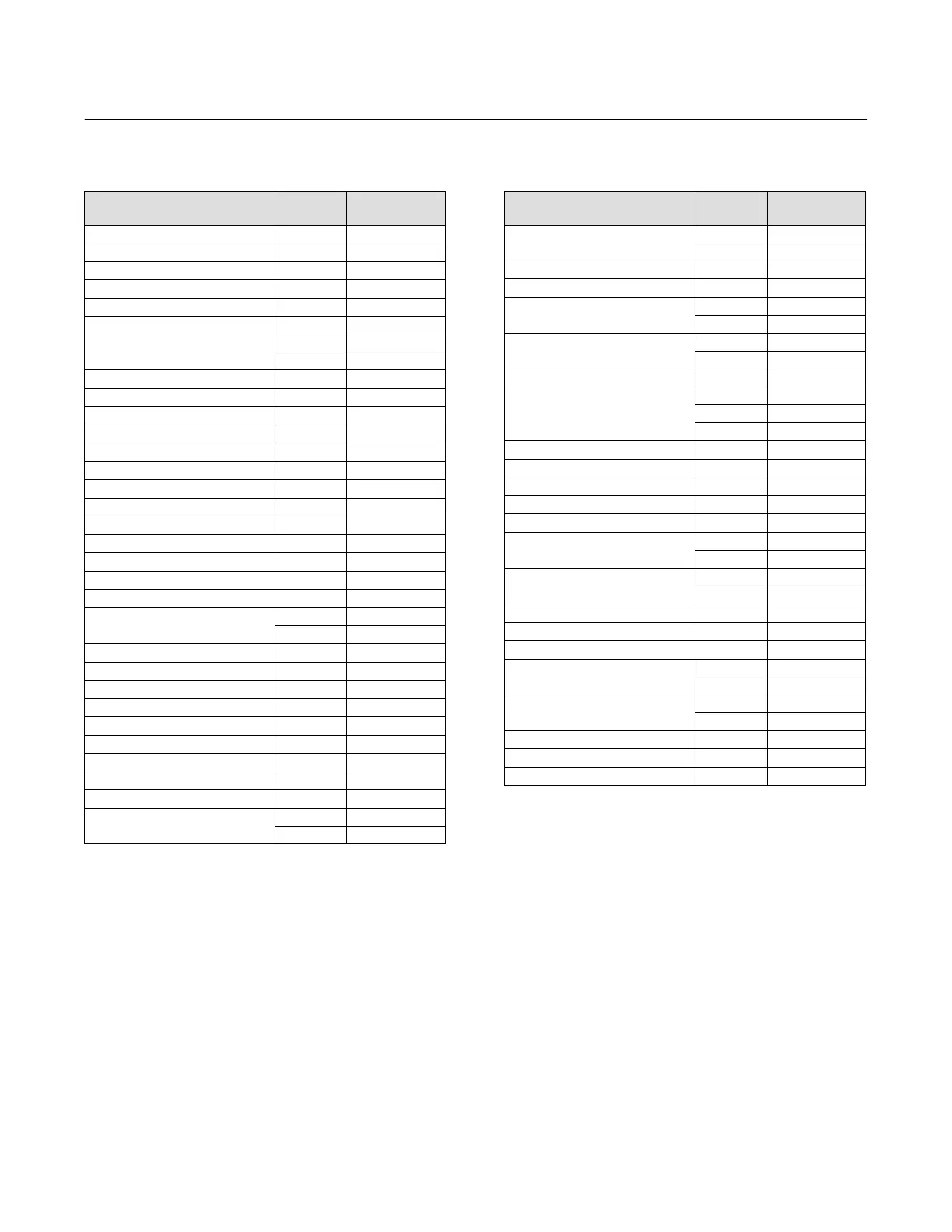
Instrument Level AC
Function/Variable
Fast‐Key
Sequence
Coordinates
(1)
Actuator Style 1‐1‐2‐2‐4 4‐C
Analog Input Calibration 1‐3‐1 3‐F
Analog Input Range Hi 1‐2‐2‐2 4‐E
Analog Input Range Lo 1‐2‐2‐3 4‐E
Analog Input Units 1‐2‐2‐1 4‐E
Auto Travel Calibration
1‐1‐2‐3‐4 4‐D
1‐3‐2 3‐F
1‐1‐1‐3 3‐C
Calibration Location 1‐3‐5 3‐G
Date 1‐2‐1‐4 3‐D
Descriptor 1‐2‐1‐3 3‐D
Device Description Revision 2‐2 2‐F
Device Identification 2‐1‐6 3‐H
Device Revision 2‐1‐2 3‐G
Feedback Connection 1‐1‐2‐2‐5 4‐C
Firmware Revision 2‐1‐3 3‐G
Hardware Revision 2‐1‐4 3‐G
HART Tag 1‐2‐1‐1 3‐D
HART Universal Revision 2‐1‐1 3‐G
Input Characterization 1‐2‐3‐6 4‐F
Instrument Level 2‐1‐5 3‐H
Instrument Mode
Hot Key‐1 1‐B
1‐1‐2‐1 3‐C
Instrument Serial Number 1‐2‐1‐6 3‐D
Integral Dead Zone 1‐2‐3‐3‐1 6‐F
Integral Limit 1‐2‐3‐3‐2 6‐F
Manual Travel Calibration 1‐3‐3 3‐F
Maximum Supply Pressure 1‐1‐2‐2‐3 4‐C
Message 1‐2‐1‐2 3‐D
Polling Address 1‐2‐1‐7 3‐E
Pressure Integral Control Enable 1‐2‐3‐4‐2 6‐G
Pressure Integral Gain 1‐2‐3‐4‐3 6‐G
Pressure MLFB Gain
1‐1‐2‐3‐2‐3 6‐D
1‐2‐3‐4‐1‐3 5‐H
Function/Variable
Fast‐Key
Sequence
Coordinates
(1)
Pressure Proportional Gain
1‐1‐2‐3‐2‐2 6‐D
1‐2‐3‐4‐1‐2 5‐H
Pressure Range Hi 1‐2‐3‐5‐1 4‐G
Pressure Range Lo 1‐2‐3‐5‐2 4‐G
Pressure Tuning Set
1‐1‐2‐3‐2‐1 6‐D
1‐2‐3‐4‐1‐1 6‐G
Pressure Units
1‐1‐2‐2‐2 4‐C
1‐2‐2‐4 4‐E
Protection Hot Key‐2 1‐B
Relay Adjust
1‐1‐1‐2 3‐B
1‐1‐2‐3‐3 4‐D
1‐3‐6 3‐G
Relay Type 1‐2‐4 3‐E
Restore Factory Settings 1‐3‐4 3‐F
Setup Wizard 1‐1‐1‐1 3‐D
Travel Integral Gain 1‐2‐3‐2‐3 6‐F
Travel Integral Enable 1‐2‐3‐2‐2 6‐F
Travel MLFB Gain
1‐1‐2‐3‐1‐4 6‐C
1‐2‐3‐2‐1‐4 6‐E
Travel / Pressure Select
1‐1‐2‐2‐1 4‐C
1‐2‐3‐1 4‐F
Travel Proportional Gain 1‐1‐2‐3‐1‐2 6‐C
Travel Sensor Adjust 1‐3‐7 3‐G
Travel Sensor Motion 1‐1‐2‐2‐6 4‐C
Travel Tuning Set
1‐1‐2‐3‐1‐1 6‐C
1‐2‐3‐2‐1‐1 6‐E
Travel Velocity Gain
1‐1‐2‐3‐1‐3 6‐C
1‐2‐3‐2‐1‐3 6‐E
Valve Serial Number 1‐2‐1‐5 3‐D
Valve Style 1‐1‐2‐2‐7 4‐C
Zero Power Condition 1‐1‐2‐2‐8 4‐C
1. Coordinates are to help locate the item on the menu tree on page 133.
 Loading...


