Instruction Manual
D103409X012
Installation
May 2013
33
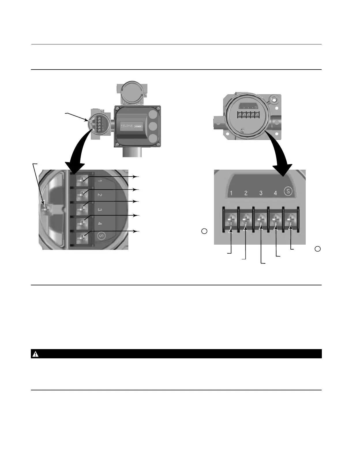
Figure 2‐25. Terminal Details for Connecting the Base Unit and Feedback Unit for Remote‐Mounted Digital Valve
Controllers
FEEDBACK CONNECTIONS
TERMINAL BOX
FEEDBACK UNIT
TO FEEDBACK UNIT TERMINAL 1
TO FEEDBACK UNIT TERMINAL 2
TO FEEDBACK UNIT TERMINAL 3
GROUND
SCREW
TERMINAL 1
TERMINAL 3
TERMINAL 2
X0131
BASE UNIT
FEEDBACK UNIT
FEEDBACK
CONNECTIONS
TERMINAL BOX
TO FEEDBACK UNIT TERMINAL 4
TERMINAL 4
TO FEEDBACK UNIT TERMINAL S
USING CABLE SHIELD
TERMINAL S
X0132
6. Connect the third wire of the 4‐conductor shielded cable between terminal 3 on the feedback unit and terminal 3
on the base unit.
7. Connect the fourth wire of the 4‐conductor shielded cable between terminal 4 on the feedback unit and terminal 4
on the base unit.
WARNING
The cable shield is typically not insulated. It is required that you insulate the cable shield prior to installation.
When connecting the cable shield in step 8 ensure that the uninsulated shield wiring does not contact the DVC6215
housing. Failure to do so can result in ground loop issues.
8. Connect the cable shield between terminal S on the feedback unit and terminal S on the base unit.
 Loading...


