Description
3
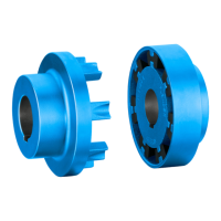
The N‑EUPEX or N‑EUPEX DS couplings described here are torsionally flexible, damping pin
couplings and are available in various types and sizes. The couplings can be used in
accordance with the ATEX Directive in potentially explosive atmospheres if they have a CE
marking.
Types A and B are fail-safe. Types ADS and BDS have no fail-safe device.
These instructions describe the assembly and operation of an N‑EUPEX or N‑EUPEX DS
coupling arranged horizontally with a shaft-hub connection made by a cylindrical or conical
bore with parallel key. Please consult Flender if you want to use a different type of installation.
Application
N‑EUPEX couplings are designed for use in all kinds of machines.
N‑EUPEX DS couplings are used for applications which require the input and output to be
disconnected from one another in the event of destruction of the flexible elements.
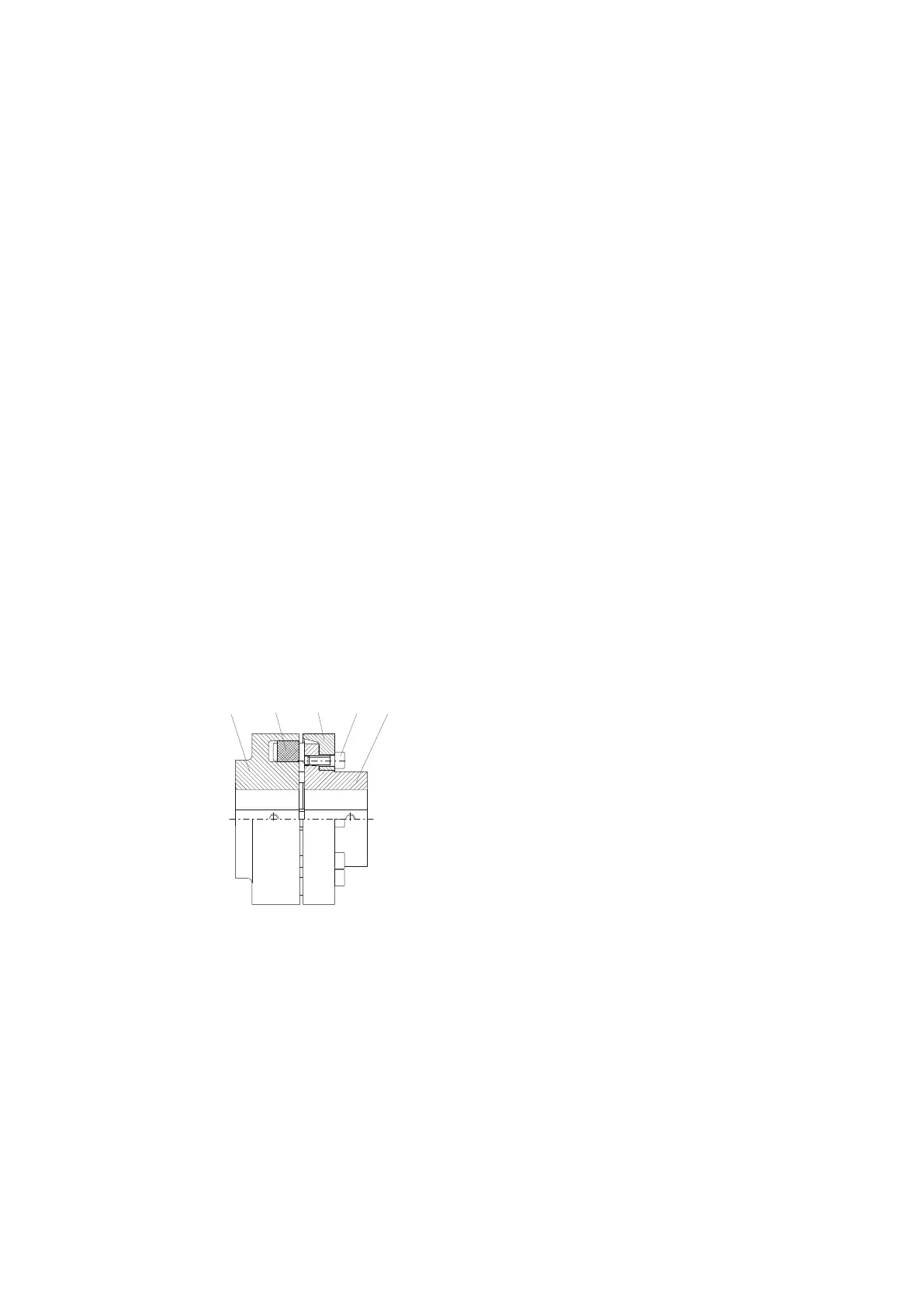
Design
The diagrams show the various types with their constituent parts and their part numbers.
1 Coupling part 1
2 Coupling part 2
3 Coupling part 3
12 Flexible element
13 Cylinder-head screw
16 Cylindrical pin
only with type A sizes 560 to 710
Figure 3-1 Type A and ADS
N-EUPEX / N-EUPEX DS 3100en
Operating Instructions 10/2017 19