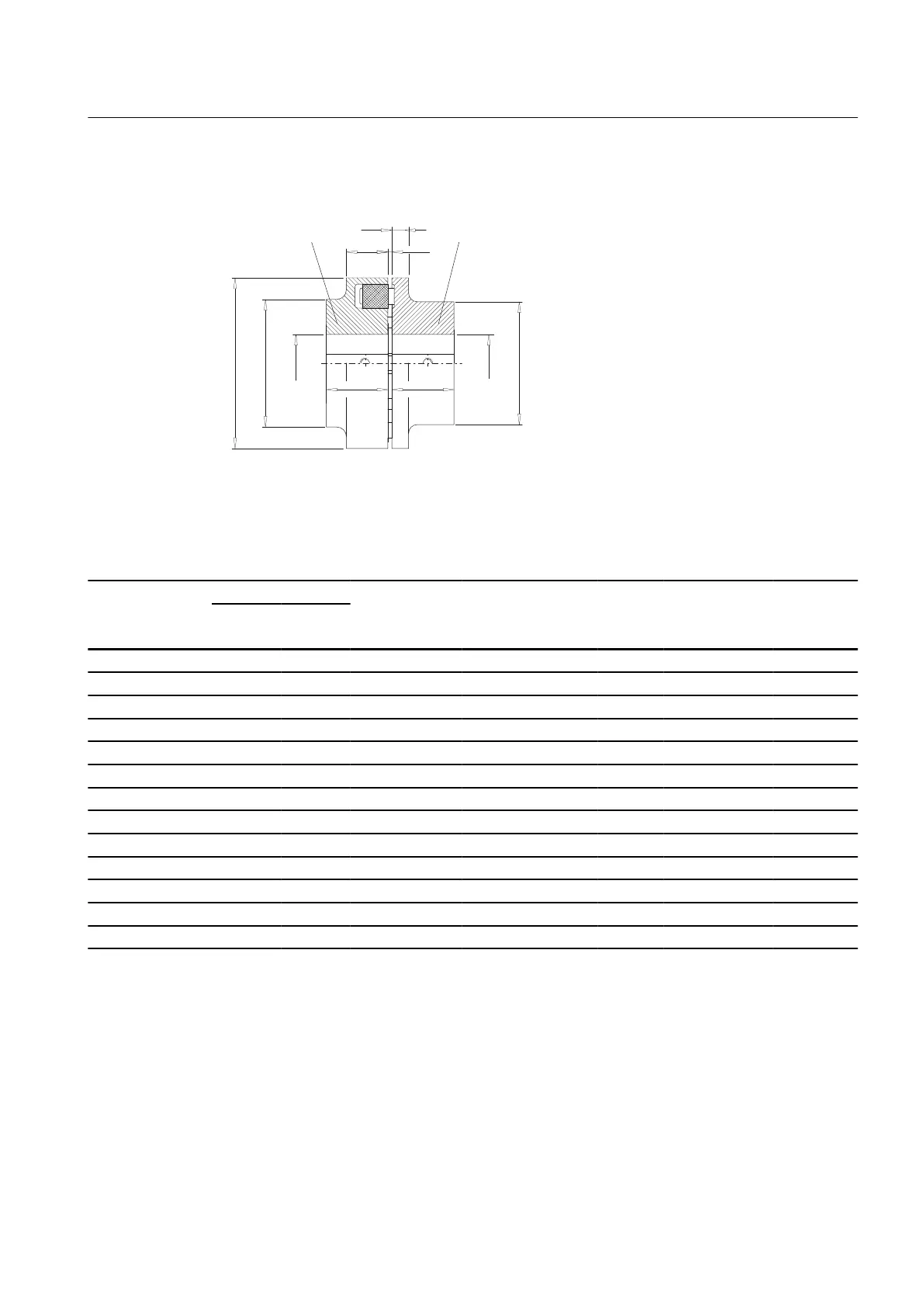
A.1.2 Type B
1/1/
'
1'
'$
'
1'
8
6
8
1 Coupling part 1
4 Coupling part 4
Figure A-2 Type B
Table A-2 Speeds, geometry data and weights of type B
Size Speed
n
max.
rpm
Maximum bore
1)
DA
mm
ND1
mm
ND2
mm
NL1 / NL2
mm
S
mm
U1
mm
U2
mm
Weight
2)
m
kg
D1
mm
D2
mm
58 7 500 19 24 58 58 40 20 2 … 4 20 8 0.4
68 7 000 24 28 68 68 50 20 2 … 4 20 8 0.54
80 6 000 30 38 80 80 68 30 2 … 4 30 10 1.3
95 5 500 42 42 95 76 76 35 2 … 4 30 12 2.2
110 5 300 48 48 110 86 86 40 2 … 4 34 14 3.3
125 5 100 55 55 125 100 100 50 2 … 4 36 18 5.2
140 4 900 60 60 140 100 100 55 2 … 4 34 20 5.6
160 4 250 65 65 160 108 108 60 2 … 6 39 20 7.8
180 3 800 75 75 180 125 125 70 2 … 6 42 20 11.5
200 3 400 85 85 200 140 140 80 2 … 6 47 24 16
225 3 000 90 90 225 150 150 90 2 … 6 52 18 20
250 2 750 100 100 250 165 165 100 3 … 8 60 18 29
280 2 450 110 110 280 180 180 110 3 … 8 65 20 38
1)
Maximum bore for parallel keyway in accordance with DIN 6885/1.
2)
Weight applies to one coupling with maximum bore.
Technical data
A.1 Speeds, geometry data and weights
N-EUPEX / N-EUPEX DS 3100en
Operating Instructions 10/2017 59