Note
Shorter maintenance intervals
If necessary, set shorter maintenance intervals depending on actual wear.
8.2 Maximum permissible torsional backlash
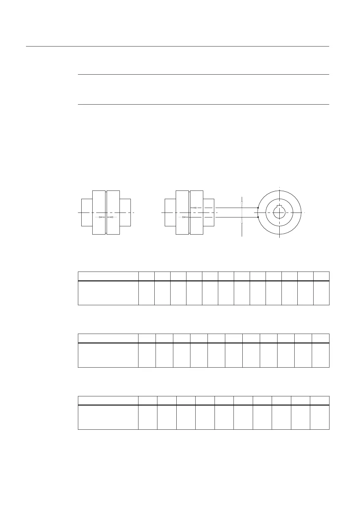
In order to calculate the torsional backlash, rotate one coupling part without applying torque
up to the stop. Mark both of the coupling halves in the way shown in the diagram below. Turn
the coupling part in the opposite direction up to the stop. The markings on both halves will then
move apart. The distance between the markings corresponds to the torsional backlash.
Figure 8-1 Markings for calculating the torsional backlash
Table 8-2 Maximum permissible torsional backlash for the types A and B (sizes 58 to 250)
Size 58 68 80 95 110 125 140 160 180 200 225 250
Maximum permissible
torsional backlash ΔS
V
[mm]
5.5 5.5 5.0 6.0 7.0 8.0 8.0 8.0 8.0 8.5 9.0 10.0
Table 8-3 Maximum permissible torsional backlash for the types A and B (sizes 280 to 710)
Size 280 315 350 400 440 480 520 560 610 660 710
Maximum permissible
torsional backlash ΔS
V
[mm]
11.5 10.5 11.5 13.0 14.0 15.5 17.5 17.5 19.5 21.0 22.5
Table 8-4 Maximum permissible torsional backlash for the types ADS and BDS (sizes 66 to 218)
Size 66 76 88 103 118 135 152 172 194 218
Maximum permissible
torsional backlash ΔS
V
[mm]
6.0 7.0 5.0 7.0 9.0 10.5 11.5 9.0 8.0 7.0
Servicing
8.2 Maximum permissible torsional backlash
N-EUPEX / N-EUPEX DS 3100en
44 Operating Instructions 10/2017