Please note the following when balancing the coupling:
● Select the balancing quality according to the application (but at least G16 in accordance
with DIN ISO 21940).
● Observe the balancing specification according to DIN ISO 21940-32.
● Machine the balancing bore on a large radius with adequate clearance to the flexible
element webs / pockets and to the cams and the outer circumference.
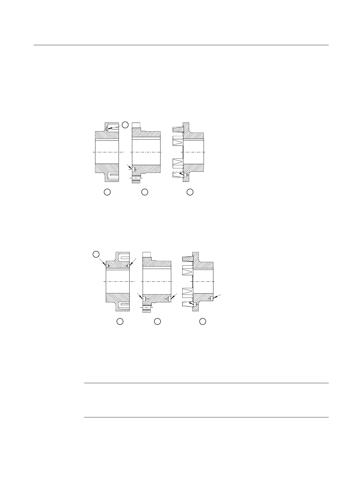
① Balancing bore
② Part 1 for N‑EUPEX or N‑EUPEX DS coupling
③ Part 2 for N‑EUPEX or N‑EUPEX DS coupling
④ Part 4 for N‑EUPEX or N‑EUPEX DS coupling
Figure 5-3 Position of the balancing bore for single-plane balancing
① Balancing bore
② Part 1 for N‑EUPEX or N‑EUPEX DS coupling
③ Part 2 for N‑EUPEX or N‑EUPEX DS coupling
④ Part 4 for N‑EUPEX or N‑EUPEX DS coupling
Figure 5-4 Position of the balancing bore for two-plane balancing
Note
A better balancing result can be achieved by balancing the coupling parts (2 and 3) when they
are bolted together as an assembly. When balancing all parts together, mark the position of
the components relative to one another.
Assembly
5.1 Preparatory work
N-EUPEX / N-EUPEX DS 3100en
Operating Instructions 10/2017 29