Table 8-5 Maximum permissible torsional backlash for the types ADS and BDS (sizes 245 to 556)
Size 245 272 305 340 380 430 472 514 556
Maximum permissible
torsional backlash ΔS
V
[mm]
6.5 7.0 8.0 6.5 7.0 10.0 12.0 14.0 16.0
8.3 Replacing wearing parts
DANGER
Danger due to bursting of the coupling
If you do not observe the information stipulated here regarding replacement of wearing parts,
this can lead to bursting of the coupling during operation. There is a risk of fatal injury from
flying fragments. Bursting of the coupling can lead to an explosion in potentially explosive
atmospheres.
● Please observe all the stipulations concerning the replacement of wearing parts.
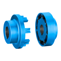
Replace the flexible elements (12) if the maximum permissible torsional backlash has been
reached. The method used to replace the flexible elements (12) varies according to the
coupling type.
Types A and ADS
Replace the flexible elements (12) without moving the coupled machines.
1. Undo the connection between coupling parts 2 (2) and 3 (3).
2. Move the coupling part 3 (3) axially.
The flexible elements (12) are freely accessible after coupling part 2 (2) has been turned.
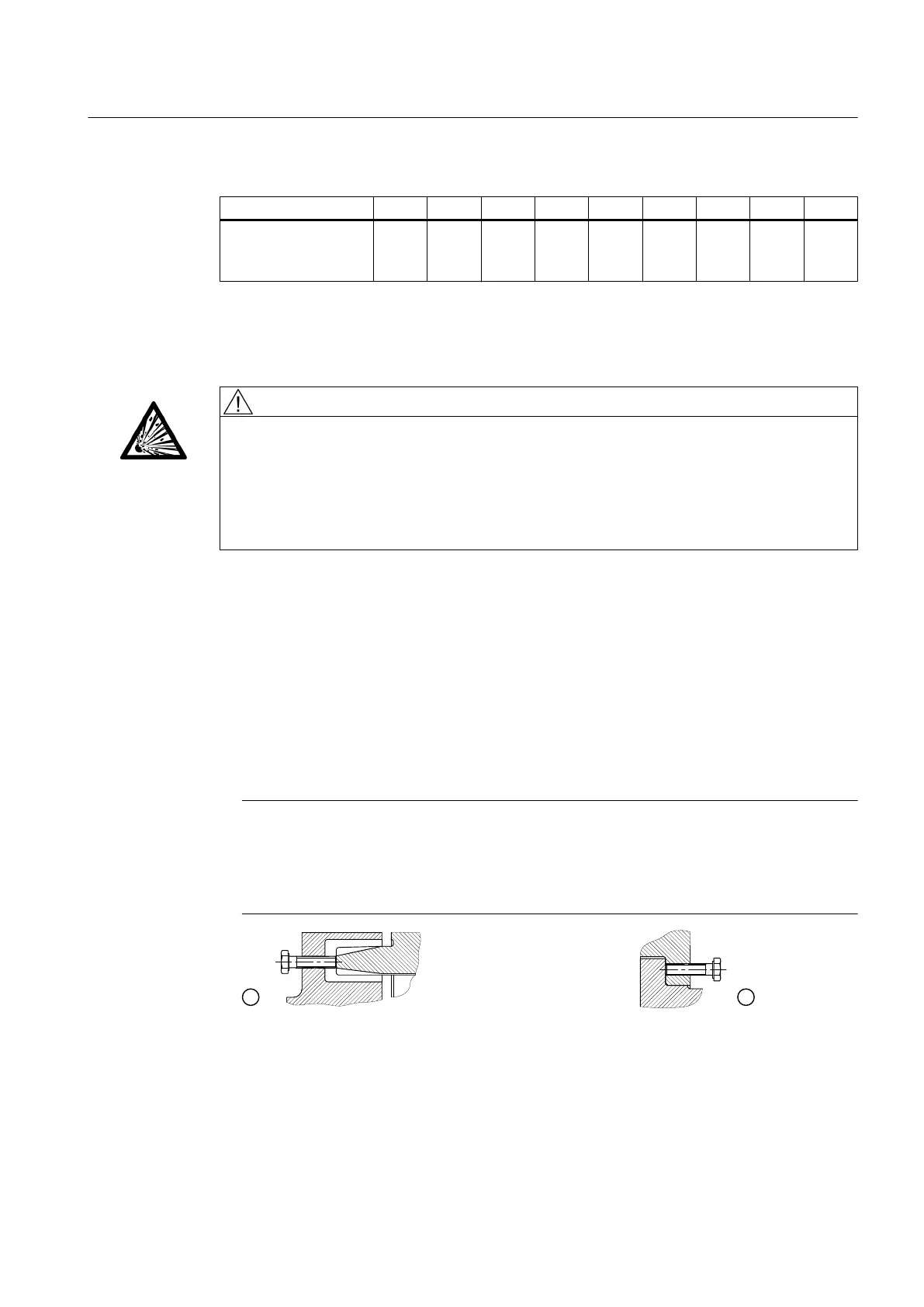
Note
Loosening coupling part 3 (3)
To make it easier to loosen coupling part 3 (3), a tapped jacking hole is machined in coupling
part 1 (1) on coupling sizes 225 to 430. As of coupling size 440, the tapped jacking hole is
machined in coupling part 3 (3).
① Tapped jacking hole in coupling part 1
② Tapped jacking hole in coupling part 3
Figure 8-2 Tapped jacking hole for loosening coupling part 3 (3)
Servicing
8.3 Replacing wearing parts
N-EUPEX / N-EUPEX DS 3100en
Operating Instructions 10/2017 45