,7$
$
'7,%7,
,7&
,7&
'&%
7,7,7,7,
ෘ'
ෘ'
ෘ'
ෘ'
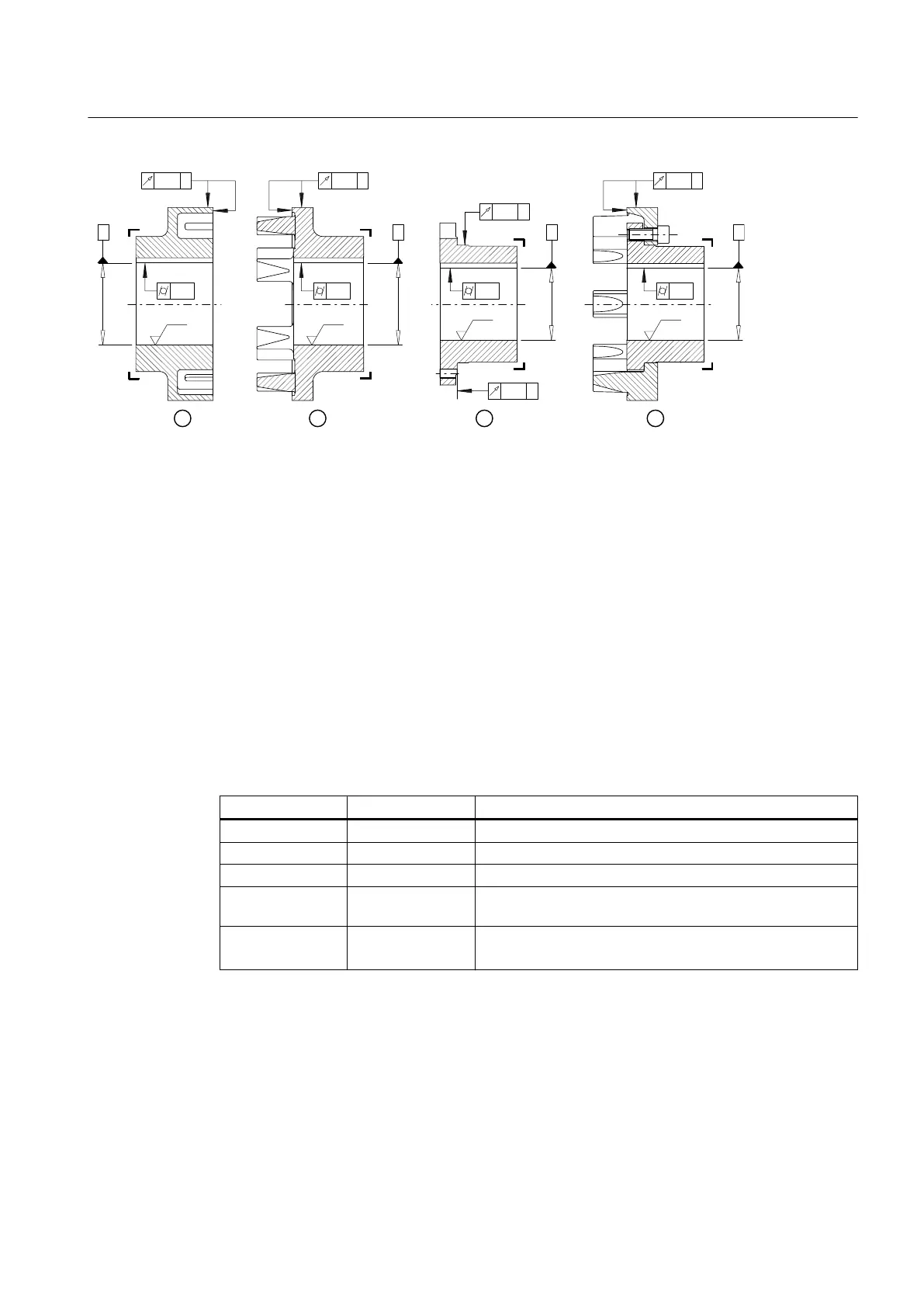
① Coupling part 1
② Coupling part 4
③ Coupling part 2
④ Coupling part 2/3
Figure 5-1 Tolerances for finished bore
5.1.2 Milling the parallel keyway
Position of the parallel keyway
The table below states the required position for the parallel keyway in the coupling parts
depending on the coupling type.
Table 5-2 Position of the parallel keyway
Coupling part Coupling Position of the parallel keyway
1 N‑EUPEX Centred between the flexible element webs
1 N‑EUPEX DS Centred between the flexible element pockets
2 N‑EUPEX Centred between the tapped holes
2 N‑EUPEX DS Centred between the tapped holes and offset relative to the
recesses for replacement of flexible elements
4 N‑EUPEX
N‑EUPEX DS
Beneath a cam
Assembly
5.1 Preparatory work
N-EUPEX / N-EUPEX DS 3100en
Operating Instructions 10/2017 25