Applicable standards
● If the coupling is intended for use under normal operating conditions, mill the parallel
keyway according to DIN 6885/1 ISO JS9.
● If the coupling is intended for reversing operation, mill the parallel keyway according to
DIN 6885/1 ISO P9.
● If you want to mill a parallel keyway that does not correspond to DIN 6885/1, please consult
Flender.
5.1.3 Machining an axial locking mechanism
The coupling part is secured by a set screw or an end plate to prevent axial movements.
Please consult Flender if you want to use an end plate.
Note the following when using a set screw:
● Diameter and axial position of the tapped hole in the hub
● Position of the tapped hole with respect to the parallel keyway
● Selection of the set screw
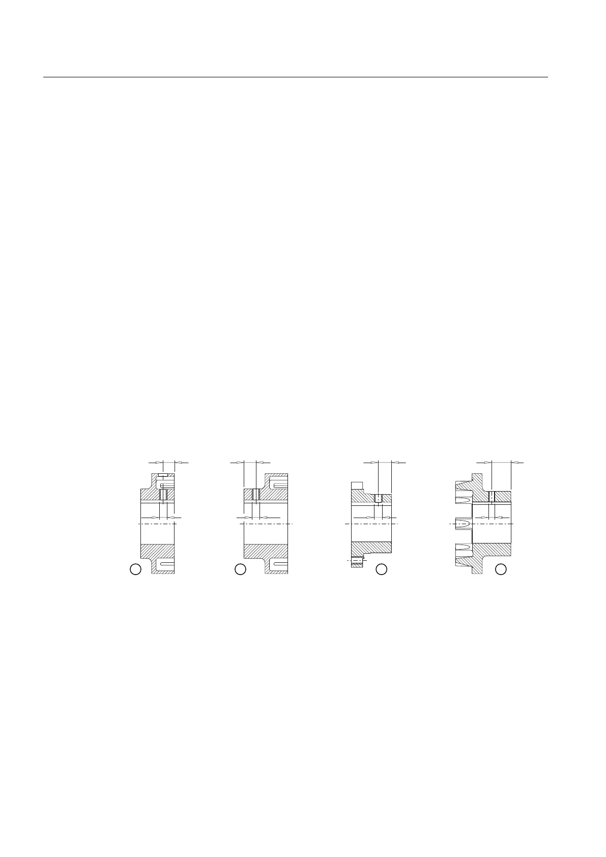
Diameter and axial position of the tapped hole in the hub
The following diagram shows the axial position of the tapped hole.
① Coupling part 1; axial position of the tapped hole up to size 125 / 135
② Coupling part 1; axial position of the tapped hole as of size 140 / 152
③ Coupling part 2
④ Coupling part 4
Figure 5-2 Diameter and axial position of the tapped hole in the hub
Assembly
5.1 Preparatory work
N-EUPEX / N-EUPEX DS 3100en
26 Operating Instructions 10/2017