5.3.2 Possible misalignment
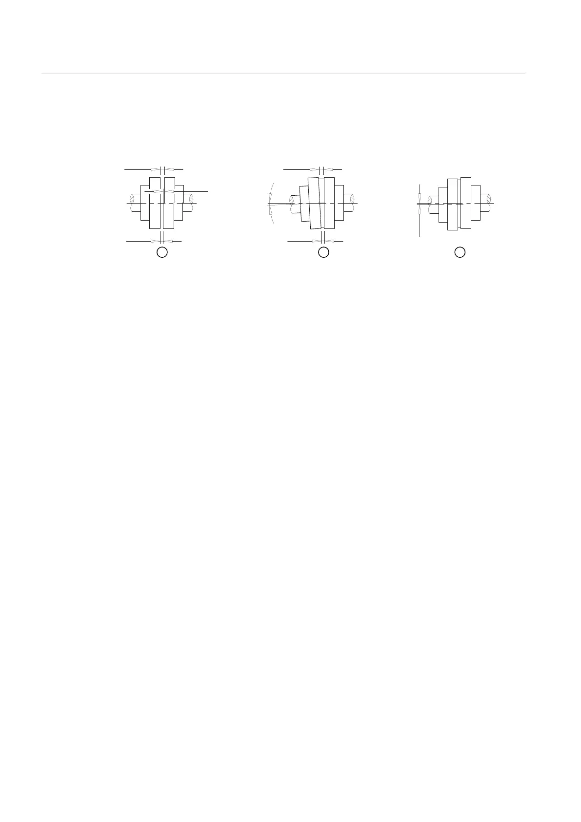
The following types of misalignment can occur:
ෙ.D
ෙ.Z
ෙ.U
6
PD[
6
PLQ
6
PLQ
6
PD[
① Axial misalignment (ΔKa)
② Angular misalignment (ΔKw)
③ Radial misalignment (ΔKr)
Figure 5-5 Possible misalignment
5.3.2.1 Axial misalignment
Set the axial misalignment ΔKa to a value within the permissible tolerance range of dimension
S.
You can find the values for dimension S in section Speeds, geometry data and weights
(Page 57).
5.3.2.2 Angular misalignment
Determine the value ΔS (ΔS = S
max
- S
min
). The determined value ΔS may not exceed the value
ΔS
perm
.
You can find the values for ΔS
perm
in section Shaft misalignment values during operation
(Page 62).
If required, you can calculate the angular misalignment ΔKw as follows:
ΔKw [rad] = ΔS / DA
ΔKw [deg] = (ΔS / DA) · (180 / π)
If required, you can calculate the permissible angular misalignment ΔKw
perm
as follows:
ΔKw
perm
[rad] = ΔS
perm
/ DA
ΔKw
perm
[deg] = (ΔS
perm
/ DA) · (180 / π)
DA in mm see section Speeds, geometry data and weights (Page 57)
ΔS
perm
see section Shaft misalignment values during operation (Page 62)
Assembly
5.3 Aligning the coupling
N-EUPEX / N-EUPEX DS 3100en
32 Operating Instructions 10/2017