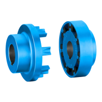
3. Remove the flexible elements (12).
4. Install the new flexible elements (12).
Please observe the information in section Use and storage of flexible elements (12)
(Page 64) when replacing flexible elements (12).
When reinstalling the coupling parts please observe the information in chapters Assembly
(Page 23) and Commissioning (Page 35).
Types B and BDS
1. In order to replace the flexible elements (12), move the coupled machines apart.
2. Remove the flexible elements (12).
3. Install the new flexible elements (12).
Please observe the information in section Use and storage of flexible elements (12)
(Page 64) when replacing flexible elements (12).
When reinstalling the coupling parts please observe the information in chapters Assembly
(Page 23) and Commissioning (Page 35).
8.4 Removing the coupling
DANGER
Danger from burners and hot coupling parts
Risk of injury due to burners and hot surfaces. Burners or hot coupling parts can lead to an
explosion in potentially explosive atmospheres.
● Wear suitable protective equipment (gloves, safety goggles).
● Ensure that the area is not at risk of explosion.
Procedure
1. Move the coupled machines apart.
2. Secure the coupling parts to prevent them from falling.
3. Remove the axial locking elements (set screw, end plate).
4. Use a suitable pulling fixture.
5. Heat up the coupling part 1 (1) and 2 (2) or 4 (4) using a burner above the parallel keyway
along its length to maximum 80 °C.
Note when doing this the temperature range of the flexible elements (12) (see sections N-
EUPEX flexible elements (12) (Page 65)and N-EUPEX DS flexible elements (12)
(Page 66)). Remove the flexible elements if necessary.
6. Pull off the coupling part. Use suitable lifting gear when doing this.
7. Check the hub bore and the shaft for damage and protect them against corrosion.
8. Replace any damaged parts.
Servicing
8.4 Removing the coupling
N-EUPEX / N-EUPEX DS 3100en
46 Operating Instructions 10/2017