FOM16 Installation Description
FOM16-V2.0-20021114
-6-
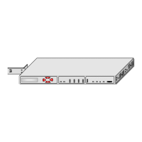
3.6 FOM16 provides audible and visual alarm contacts that use relays to activate a circuit loop
between each alarm contact point and the common point in case of an alarm. The pin
assignments of the rear female DB-9 connector are shown in Fig.11.
MJV: Visual Major alarm
MJA: Audible Major alarm
MNV: Visual Minor alarm
MNA: Audible Minor alarm
ALMCOM Common Point
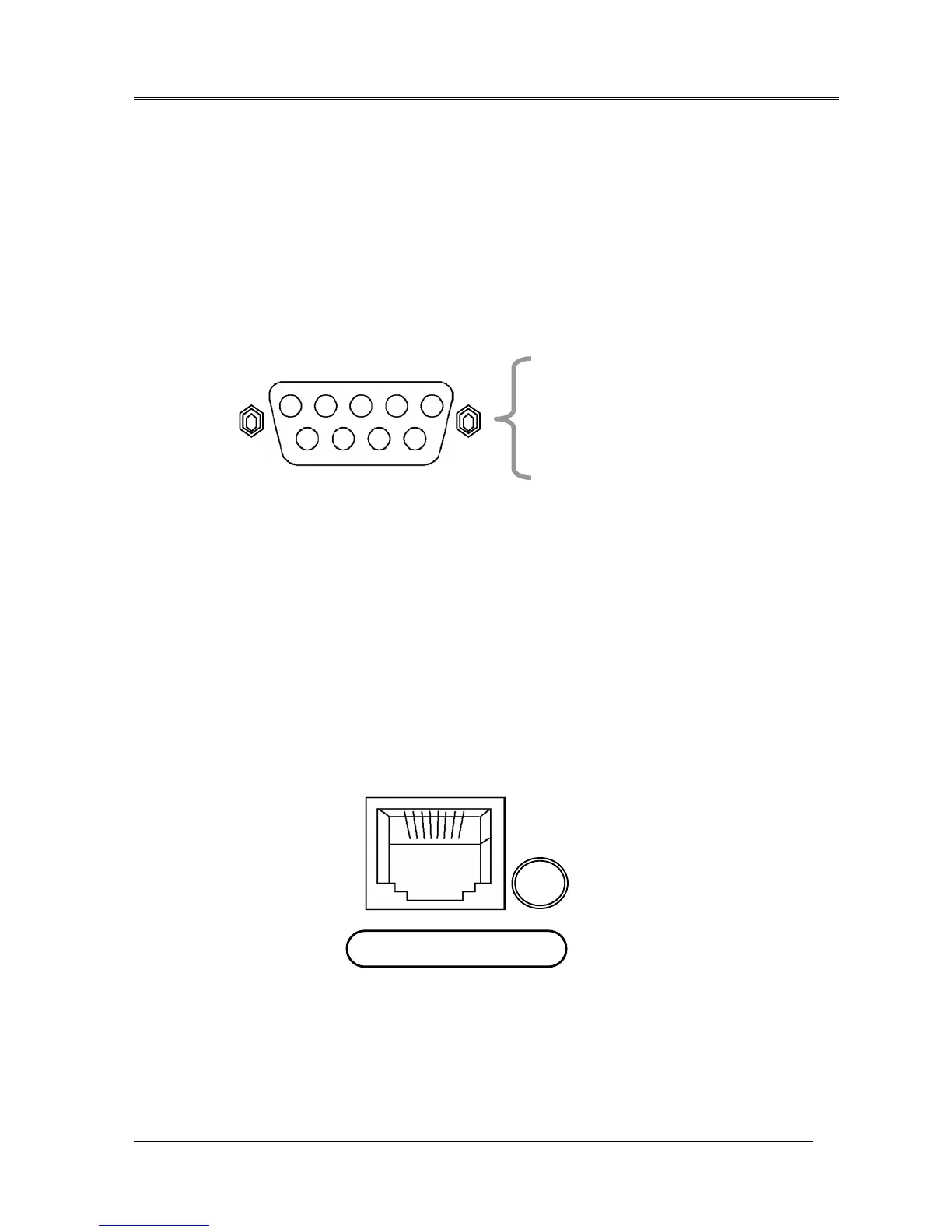
3.7 FOM16 is equipped with a rear LAN port that is an RJ-45 connector. This port operates at a
rate of 10 Mbps over an ETHERNET cable. Pin assignment is shown in Fig.12.
Fig.12 LAN port of an RJ-45 connector
LAN
1ÅÆ8
PIN1 – TX+ (transmit positive out)
PIN2 – TX- (transmit negative out)
PIN3 – RX+ (receive positive in)
PIN6 – RX+ (receive negative in)
Alarm Contact
pin5 - MJA
pin9 – MJV
pin4 – MNA
pin8 – MNV
pin3 - ALMCOM
14 3 5
6
9
7
8
2
Fig.11 Alarm contact pin assignment