FOM16 Installation Description
FOM16-V2.0-20021114
-7-
4. Optical Installation
4.1 FC/PC connectors are used for optical interfaces. “IN” and “OUT” are used to indicate the
directions of laser beam input and output. ”O-W” means the optical working pair and “O-P” the
optical protection pair. The working pair of near end must be connected with that of far end and
the same for the protection pair.
4.2 Eye damage may be caused by a broken fiber or by an unterminated connector if the
laser beam is viewed directly or with improper optical instruments.
4.3 When planning the routing of fiber optic cables, avoid sharp bends.
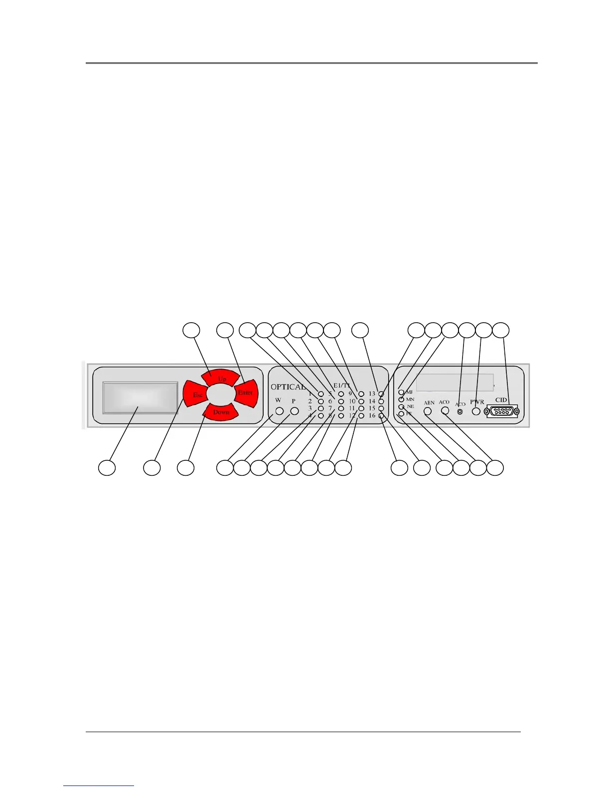
5. Front Panel Indicator
Fig.11 shows the front view of the FOM16, and Table 1 lists the functions of the FOM16
controls, connectors, and indicators, located in the FOM16 front panel. The index numbers in
Table 1 correspond to the item numbers in Fig.13.
Fig.13 FOM16 Front View
7
10
11 14 151 18 19 22 23 26 27 28 29
3
5 6
1213 16 17 20 21 24 25 30 31 324 2 8 9