FOM16 Installation Description
FOM16-V2.0-20021114
-8-
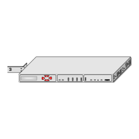
Table.1 FOM16 Controls, Connectors and Indicators
NO. Controls or Indicators Function Description
1
LCD
display window
Two by twenty (2×20) characters LCD to show menu items.
2 Enter key pad Used to move down the menu tree or enable a selection.
3 ESC key pad Returns the operation to an upper layer menu.
4 Up key pad Shows the other menu item in the same level.
5 Down key pad Shows the other menu item in the same level.
6 Optical Working
indicator
GREEN: when the optical working link interface is in use.
RED: when the optical working link interface reports loss or
out-of –frame of input signal.
YELLOW: when the optical working link interface is installed but
in stand by state.
7 Optical Protection
indicator
Same functions as item 6 for the optical protection link interface.
8 Ch1 indicator
9 Ch2 indicator
10 Ch3 indicator
11 Ch4 indicator
12 Ch5 indicator
13 Ch6 indicator
14 Ch7 indicator
15 Ch8 indicator
16 Ch9 indicator
17 Ch10 indicator
18 Ch11 indicator
19 Ch12 indicator
20 Ch13 indicator
21 Ch14 indicator
22 Ch15 indicator
23 Ch16 indicator
GREEN: when the corresponding tributary interface is in use.
RED: when the corresponding tributary interface reports loss of input
signal.
OFF: when the corresponding tributary interface is out of service.
Blinking GREEN: when the corresponding tributary interface is in
abnormal operation, i.e., local loopback or remote loopback is
activated.