FOM16 Installation Description
FOM16-V2.0-20021114
-4-
3. Electrical Installation
3.1 FOM16 can be either AC- or DC-powered. If both AC and DC are fed at the time, The AC
power is selectable internally first and the DC power is used as a back up power source.
3.2 Use the rear left AC power connector to connect to an AC power outlet capable of furnishing a
supply voltage for either 110 or 220 VAC.
3.3 Use the rear right DC power connector to connect to a DC power source capable of furnishing
a supply voltage -48 VDC.
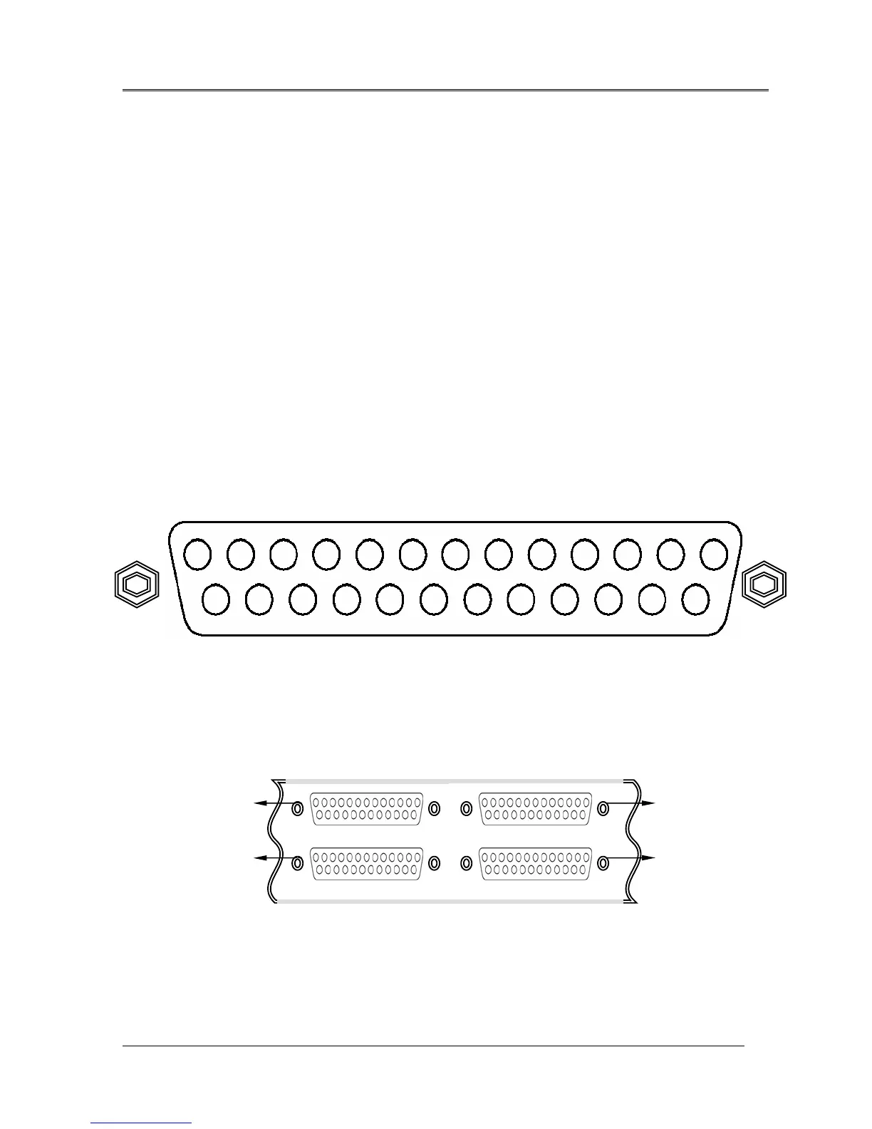
3.4 FOM16 consists of 16 E1 tributaries, i.e. CH1 ~ CH16. Each E1 tributary uses 4 pins, i.e.
Input Tip/Ring and Output Tip/Ring. Each rear DB-25 connector contains a 4-E1-tributary
group, that is, there are 16 pins designated for 4 E1 tributaries and 9 pins for frame ground
(FGND). The pin assignments are shown in the Fig.7 and Fig.8.
3.5 For the unbalance interface, each E1 tributary has two BNC connectors designated TXTIP
(transmit output) and RXTIP (receive input), as shown in Fig.9 and Fig.10.
Fig.8 DB-25 connectors and 16 E1 tributaries
GROUP A CH1~CH4 Æ CH1 ~ CH4
GROUP B CH1~CH4 Æ CH5 ~ CH8
CH1 ~ CH4
CH5 ~ CH8
CH9 ~ CH12
CH13 ~ CH16
GROUP A
GROUP B GROUP D
GROUP C
GROUP C CH1~CH4 Æ CH9 ~ CH12
GROUP D CH1~CH4 Æ CH13 ~ CH16
1417 16 15 1821 20 1922 25 24 23
43 2 597610 13 12 11 8
Output
Ring4
Output
Tip4
Output
Ring3
Output
Tip3
Output
Ring2
Output
Tip2
Output
Ring1
Output
Tip1
Intput
Ring4
Intput
Tip4
Intput
Ring3
Intput
Tip3
Intput
Ring2
Intput
Tip2
Intput
Ring1
Intput
Tip1
FGNDFGND FGNDFNGD
FGND FGNDFGND FNGD
FGND
Fig.7 DB-25 connector and 4 E1 tributaries
1