Do you have a question about the FlexGain PLEX and is the answer not in the manual?
Details the document version history and changes made.
Overview of the document's purpose and scope.
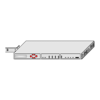
Describes the multiplexer's application and general device information.
Lists the key functions and peculiar characteristics of the multiplexer.
Provides ordering details for basic modules and daughter boards.
Details the overall description of the multiplexer device.
Provides general operational information for the device.
Offers a concise overview of the device's operational flow.
Describes the front panel interfaces and status LEDs of the device.
Explains how the device signals alarms and the behavior of LEDs and relays.
Details the operation modes and features of the E1 interface.
Describes the V.35 interface, its role as DCE, and clocking.
Explains the Ethernet interface usage for configuration and software download.
Details the mapping of voice channels to daughter board interfaces.
Covers different signaling methods supported by the device in PCM modes.
Discusses the three clock sources supported by the multiplexer.
Describes the internal clock source and its configuration.
Explains the E1 clock mode and associated alarms.
Details the external clock source synchronization options.
Explains codirectional and contradirectional synchronization for the V.35 interface.
Provides warnings on configuring clock parameters based on requirements.
Describes duplex byte transmission and cross-connection of E1 streams.
Outlines the methods for multiplexer management.
Details local management via RS-232 terminal and required parameters.
Explains network management using Ethernet and TELNET protocol.
Explains how to check device interaction using test loops.
Describes the two types of E1 loops for testing local device performance.
Details the local loops supported on the V.35 interface.
Explains CRC4 error monitoring activation for performance evaluation.
Describes the three mechanical designs of the device.
Details the Sub-Rack design, its components, and mounting.
Describes the Mini-Rack design, housing, and daughter board installation.
Explains the Stand Alone design, its casing, and power supply.
Provides the installation and connection procedure for multiplexers.
Details the configuration procedures for the devices.
Explains the command structure based on ITU-T Rec. M.3400.
Provides detailed descriptions of various device commands.
Outlines the rules for describing commands with parameters and syntax.
Explains how to manage Sub-Rack devices via the control bus.
Details management sessions for Mini-Rack and Stand Alone devices.
Describes commands related to performance management.
Covers commands for fault and maintenance management.
Lists commands for configuring module settings and ports.
Details commands for managing Ethernet and network settings.
Explains how to download software using the NetLoader program.
Details software download via RS-232 using the X-modem protocol.
Describes software download over Ethernet using X-modem or TELNET.
Describes the RINGER unit for generating FXS ring signals.
Explains the FG-Plex-E1 board for expanding E1 ports.
Details the FXO unit for connecting to PBX subscriber ports.
Describes the FXS unit for connecting subscriber equipment and telephones.
Explains the E&M unit for voice signals and signaling processing.
Describes the pins and signals of the power connector.
Details the pins and signals of the monitor connector.
Describes the pins and signals for the E1 interface.
Details the pins and signals for the Ethernet interface.
Describes the pins and signals for FXS and FXO interfaces.
Details the pins and signals for the E&M interface.
Describes the pins, circuit numbers, and signals of the V.35 interface.
| Connectors | LC/UPC |
|---|---|
| Signal Type | Optical |
| Operating Temperature | 0°C to 50°C |
| Category | Optical Multiplexer |
| Input Impedance | 50 Ω |
| Output Impedance | 50 Ω |