User’s manual FlexGain Plex, V2
Version 1.3
16 from 99
1.4 Description of the FlexGain Plex ,V2 multiplexer.
1.4.1 General information on the device operation.
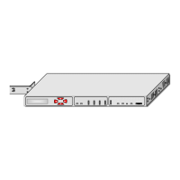
The FlexGain Plex, V2 multiplexer is a highly integrated device intended for
multiplexing up to eight analogue voice channels, the V.35 data transmission channel into
E1 G.703 streams. The use of a powerful HDB3 line encoding allows one to connect to it
the equipment located at a distance of up to two kilometers (by using a 1.2-mm cable). The
FlexGain Plex, V2 multiplexer is a valuable device of the FlexGain family, which provides
interaction with other devices of the FlexGain and FlexDSL families.
The structural scheme of the device is presented in Fig. 4.
1.4.2 Brief description of the device operation.
Signals from the subscriber (station) equipment, connected to analogue interfaces
15.1-15.4 and 17.1-17.4 of daughter boards 15 and 17, after the analogue-to digital
conversion on the codex, which is embedded in the daughter boards, are fed in a digitized
form to interfaces of daughter boards 14 and 16, which perform mechanic and electric
coupling of the boards with the basic motherboard of the device. Cross-connect matrix 7
provides two-way cross-connection of signals between time slots of E1 streams and:
• Interfaces of daughter boards 14 and 16;
• V.35 framer 12.
The cross-connect of time slots of E1 streams is performed according to the current
configuration of the multiplexer. The cross-connected output streams are fed to output
framers 5 and 41, which buffer and equate data, form frame alignment and multiframe
alignment of the stream structure, calculate the CRC4 check sum, insert national Sa bits
into the corresponding bit fields of the zeroth TS of the stream. The structures of FAS,
MFAS and CRC4 of the formed stream correspond to ITU-T Rec. G.704.
Signals from framers 5 and 41 are transmitted to microchips of output network
interfaces 2 and 38, where TTL levels are converted into the HDB3 line code. Then, the
signal via the circuit of galvanic separation and protection 1 and 37 is fed to the E1-port
interface. The input E1 stream, which is transmitted from the circuit of galvanic separation
and protection 3 and 39 is fed to receivers of network interfaces 4 and 40. The receiver
performs the following:
• suppresses noises;
• recovers clock signals from the input E1 stream;
• converts signals into the levels of CMOS logics.