Camera parts
12
12.5.2 Explanation
This table gives an explanation of the power LED indicator:
Type of signal Explanation
The LED is off. The camera is off.
The LED is green. The camera is on.
12.6 Laser pointer
12.6.1 General
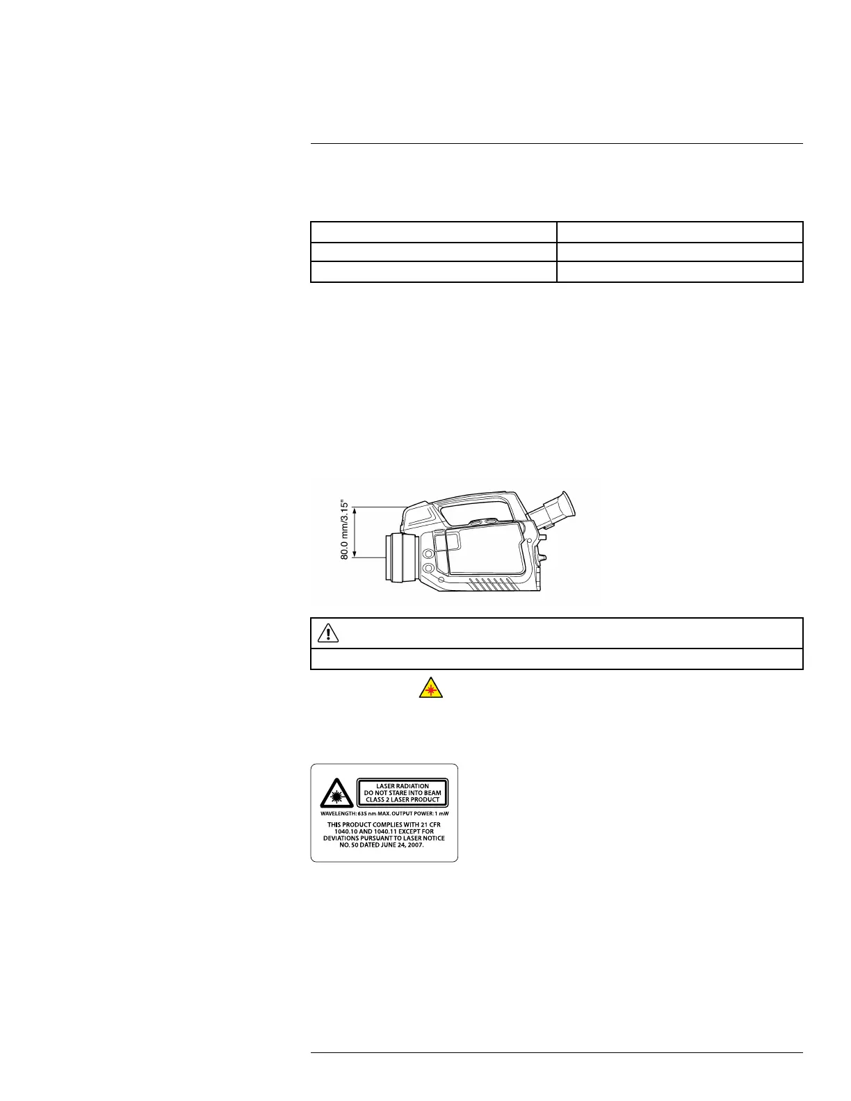
The camera has a laser pointer. When the laser pointer is on, you will see a laser dot ap-
proximately 80 mm (3.15″) above the target.
12.6.2 Figure
This figure shows the difference in position between the laser pointer and the optical cen-
ter of the infrared lens:
WARNING
Do not look directly into the laser beam. The laser beam can cause eye irritation.
Note The symbol is displayed on the screen when the laser pointer is on.
12.6.3 Laser warning label
A laser warning label with the following information is attached to the camera:
12.6.4 Laser rules and regulations
Wavelength: 635 nm. Maximum output power: 1 mW.
This product complies with 21 CFR 1040.10 and 1040.11 except for deviations pursuant
to Laser Notice No. 50, dated June 24, 2007.
#T559157; r. AH/45951/45951; en-US
33
 Loading...