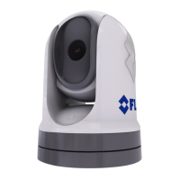
5.Placetherubberbasesealonthebottomoftheriser.
6.Slideaatwasher,andthenaspringwasher,ontoeachstud.
7.Securethecamerabodytotheriserwiththesuppliednuts,ensuringthatthesealremains
correctlypositionedonthecamera’sbase.
Tightenthenutstoatorqueof3.7N·m(2.7lbf·ft).
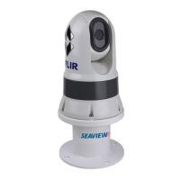
8.Connectthepowersupplycable,BNCcableandnetworkcabletothecamera,thenloop
thecablesroundwithintheriserbasesothattheycanbethreadedthroughthebottomof
theriser,andintothecableroutingholedrilledinthemountingsurface.
9.Ensuretheriser-basesealispositionedcorrectly,andthenfastenthecamera-riser
assemblytothemountingsurfaceusingfastenersappropriateforthesurface’sthickness
andmaterial.Donotusethreadlockingcompound,asthismaydamagetheplasticriser.
Y oumustensureawatertightsealbetweentheriserbaseandthemountingsurface.Y ou
mayuseamarine-gradesealantasanalternativetothesuppliedmountinggasket.
Note:
•Ifitisnotpossibletoroutethecameracablesthroughthemountingsurface,cutahole
inthesideoftheriser,androutethecablesthroughtherisersidewall.Youmayneedto
loopthecablesaroundwithintheriserbase,sothattheycanbepassedthroughthe
holeyouhavecutinthesideoftheriser.
•Ifroutingthecameracablesthroughtherisersidewall,andthecameraismounted
ball-up,doNOTsealtheriserbasewitheitherthesuppliedgasket,orsealant.Sealing
mayresultinwaterpoolinginsidetheriser.
•Ifroutingthecameracablesthroughtherisersidewall,andthecameraismounted
ball-down,doNOTsealtheconnectionbetweenthecamerabaseandthetopsurfaceof
theriserwiththesuppliedgasket.Sealingmayresultinwaterpoolinginsidetheriser.
36