EasyManua.ls Logo

FLIR M300C - User Manual

FLIR M300C
110 pages
Print Icon
To Next Page IconTo Next Page
Loading...
INSTALLATION & OPERATION
INSTRUCTIONS
SERIES
© 2019 FLIR Systems, Inc.
English (en-US) | Date: 10-2019 | Document number: 71004-2

Table of Contents

Questions and Answers

  • J
    Joseph NguyenAug 9, 2025
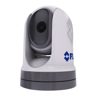
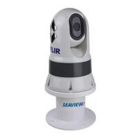
    How to fix FLIR Thermal camera when video is not displayed?
    • B
      boonesherriAug 9, 2025
      If your FLIR Thermal camera isn't displaying video, there are several potential causes. First, the camera might be in Standby mode; use the camera controls (either the thermal camera application or JCU) to wake it. Also, check the thermal camera network cables (RayNet or Ethernet) to ensure they are securely connected. Finally, verify the power connections to the camera and JCU / PoE injector (if used), ensure the power switch/breaker is on, and check the fuse/breaker state.
  • E
    Elizabeth HughesAug 14, 2025
    What to do if FLIR Thermal camera controls are erratic or unresponsive?
    • N
      Natalie DiazAug 14, 2025
      If you're experiencing erratic or unresponsive controls on your FLIR Thermal camera, start by checking that the controller and thermal camera are correctly connected to the network, either directly or via a Raymarine network switch. Also, ensure that no other controllers are in use at the same time, as this can cause control conflicts. Finally, check the power and network cabling to the controller and PoE injector (if used with an optional Joystick Control Unit).
  • L
    Luis KellerAug 21, 2025
    Why is the image on my FLIR Thermal camera too dark or too light?
    • R
      Randy HollowayAug 21, 2025
      If the image on your FLIR Thermal camera appears too dark or too light, first adjust the display brightness controls. If that doesn't resolve the issue, the Scene Mode might not be appropriate for the current conditions. Try using the SCENE button to select a different mode that better suits the environment, especially if there's a very cold background like the sky.
  • D
    Dr. Daniel HallAug 27, 2025
    How to control FLIR Thermal camera from Raymarine display?
    • J
      Janice RangelAug 27, 2025
      To control your FLIR Thermal camera from a Raymarine display or keyboard, make sure the thermal camera application is running on the multifunction display, rather than the video application, which lacks camera controls.
  • C
    Carl MartinezSep 2, 2025
    Why is the image inverted (upside down) on my FLIR Thermal camera?
    • T
      Terry MatthewsSep 2, 2025
      If the image on your FLIR Thermal camera is inverted (upside down), the camera’s “Ball down” setting is likely incorrect. Ensure that the Ball down setting is set correctly.

Summary

Chapter 1: Important Information

Chapter 2: Document and product information

Product overview

Description of M300 single payload variant and its imaging core types.

M300 (dual payload)

Description of M300 dual payload variant and its imaging cores.

Chapter 3: Installation

General location requirements

Key considerations for choosing a suitable mounting location for the product.

Compass safe distance

Advice on maintaining distance from magnetic compasses to avoid interference.

Camera mounting

Location requirements and general guidance for mounting the camera.

JCU-2 Mounting

Location requirements for mounting the JCU-2 control unit.

Chapter 4: Connections

General cabling guidance

Recommendations for cable types, routing, strain relief, and circuit isolation.

Connections overview

Overview of the product's connectors.

Connecting cables

Step-by-step instructions for connecting cables to the product.

Video connections

Details on distributing video output to multiple devices simultaneously.

Typical systems

Examples of typical system configurations for camera integration.

Network connections

Details on connecting the camera to a vessel's IP network.

Non-RayNet systems

Examples of network connections for vessels without RayNet or MFD.

RayNet systems with Raymarine LightHouse 3 multifunction displays (MFDs)

Examples of network connections using Raymarine MFDs.

Single-camera system with Raymarine MFD and JCU

Network setup for camera control using Raymarine MFD and JCU.

Power connection

Requirements and overview for connecting the camera to a power source.

Power distribution

Recommendations and best practices for distributing power to the product.

Implementation - direct connection to battery

Instructions for connecting the product directly to a vessel's battery.

Grounding

Guidance on proper grounding for the system.

In-line fuse and thermal breaker ratings

Specifies the required in-line fuse and thermal breaker ratings.

Chapter 5: Camera control options and status icons

Camera control

Controls for pan, tilt, and zoom of the camera.

Chapter 6: Web interface operation

Web browser user interface overview

How to use a web browser to communicate with and configure the camera.

Setting up a network connection to the camera

Steps to establish a network connection between an IP device and the camera.

Logging in to the Web browser user interface

How to log in to the camera's web interface using default credentials.

Camera settings menus

Accessing and configuring various camera settings via the web interface.

Troubleshoot

Procedure for setting a static IP address for the camera's network.

Chapter 7: JCU-2 operation

JCU-2 controls overview

Overview of the JCU-2's joystick and button controls for camera management.

Configuring JCU-2 user-programmable buttons (UPBs)

How to configure user-programmable buttons via the camera's web interface.

Chapter 8: MFD operation

ClearCruise thermal analytics

Intelligent thermal analytics for audible/visual alerts on non-water objects.

Auto-tracking

Setting the camera to automatically track targets like man overboard or AIS.

Chapter 10: System checks and troubleshooting

Thermal camera troubleshooting

Common problems, causes, and solutions for thermal camera issues.

Chapter 11: Technical specification

M300 Series cameras

Detailed technical specifications for the M300 Series cameras.

Video specification

Technical details of the video output from the M300 Series cameras.

JCU-2

Technical specifications for the JCU-2 joystick control unit.

FLIR M300C Specifications

General IconGeneral
Frame Rate30 Hz
Power Supply24 VDC
EnvironmentalIP66
Sensor TypeUncooled VOx Microbolometer
Thermal Sensitivity< 50 mK
Resolution640 x 512
Field of View24° x 19°
Temperature Range-40 °C to 2000 °C
Optical Zoom1x - 4x
Digital Zoom8x
Video OutputEthernet
Operating Temperature-40°C to +55°C
Storage Temperature-40°C to +70°C
Spectral Range7.5 - 13.5 µm
FocusManual or Auto

Related product manuals