Description
Connectsto:
3
Connectionto12V/24Vpowersupply.
Vessel’spowersupply.
4
Redcable(positive)
Powersupply’spositiveterminal
5
InlinefuseWaterprooffuseholdercontaininga
suitably-ratedinlinefuse(refertoInline
fuseandthermalbreakerratings).
6
Blackcable(thickblackwire)(negative)
Powersupply’snegativeterminal
Powerdistribution
Recommendationsandbestpractice.
•Theproductissuppliedwithapowercable,eitherasaseparateitemoracaptivecable
permanentlyattachedtotheproduct.Onlyusethepowercablesuppliedwiththeproduct.
DoNOTuseapowercabledesignedfor,orsuppliedwith,adifferentproduct.
•RefertothePowerconnectionsectionformoreinformationonhowtoidentifythewiresin
yourproduct’spowercable,andwheretoconnectthem.
•Seebelowformoreinformationonimplementationforsomecommonpowerdistribution
scenarios:
Important:
•Whenplanningandwiring,takeintoconsiderationotherproductsinyoursystem,some
ofwhich(e.g.sonarmodules)mayplacelargepowerdemandpeaksonthevessel’s
electricalsystem,whichmayimpactthevoltageavailabletootherproductsduringthe
peaks.
•Theinformationprovidedbelowisforguidanceonly,tohelpprotectyourproduct.It
coverscommonvesselpowerarrangements,butdoesNOTcovereveryscenario.Ifyou
areunsurehowtoprovidethecorrectlevelofprotection,pleaseconsultanauthorized
dealerorasuitablyqualiedprofessionalmarineelectrician.
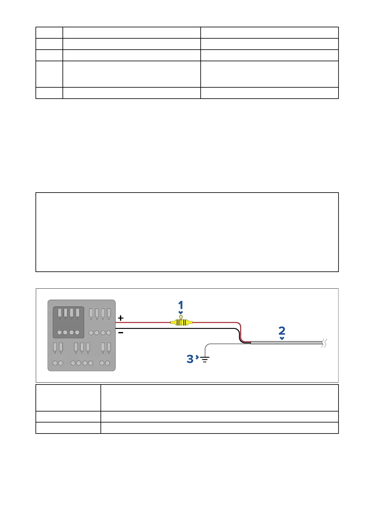
Implementation—connectiontodistributionpanel(Recommended)
1
Waterprooffuseholdercontainingasuitably-ratedinlinefusemust
betted.Forsuitablefuserating,referto:In-linefuseandthermal
breakerratings.
2
Productpowercable.
3
Drainwireconnectionpoint.
•Itisrecommendedthatthesuppliedpowercableisconnectedtoasuitablebreakeror
switchonthevessel'sdistributionpanelorfactory-ttedpowerdistributionpoint.
•Thedistributionpointshouldbefedfromthevessel’sprimarypowersourceby8AWG
(8.36mm
2
)cable.
•Ideally,allequipmentshouldbewiredtoindividualsuitably-ratedthermalbreakersorfuses,
withappropriatecircuitprotection.Wherethisisnotpossibleandmorethan1itemof
equipmentsharesabreaker,useindividualin-linefusesforeachpowercircuittoprovide
thenecessaryprotection.
60