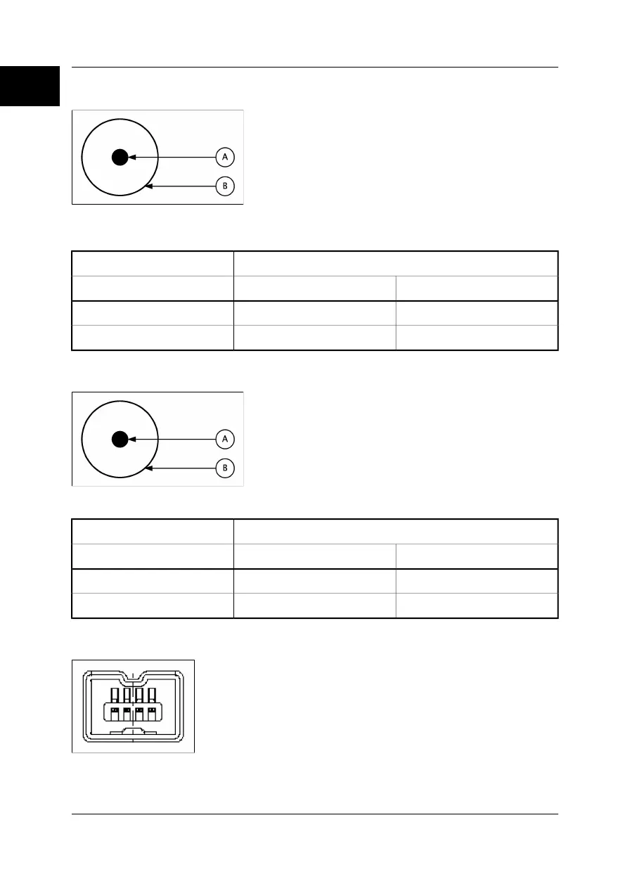
16.11.3 Power connector
10402503;a1
Figure 16.4 Pin configuration for power connector (on camera – operator’s side). A: Center pin; B:
Chassis
2.5 mm DCConnector type:
Pin numberTypeSignal name
CENTER PINPOWER+12V
CHASSISPOWERGND
16.11.4 CVBS connector
10402503;a1
Figure 16.5 Pin configuration for CVBS connector (on camera – operator’s side). A: Center pin; B: Chassis
RCA/PHONOConnector type:
Pin numberTypeSignal name
CENTER PINVIDEOCVBS
CHASSISPOWERGND
16.11.5 FireWire connector
10402303;a1
Figure 16.6 Pin configuration for FireWire connector (on camera – operator’s side)
16
146 Publ. No. 1557954 Rev. a155 – ENGLISH (EN) – February 7, 2006
16 – Technical specifications & dimensional drawings
 Loading...