LTQ008 – LTQ230 Series 3-Phase Products User Instructions – AIIOM000165 EN
Page 22 of 40
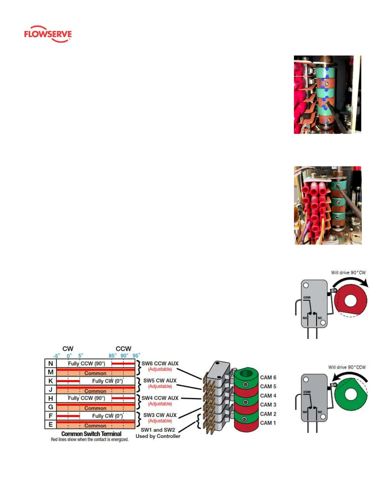
5.8.3 Adjusting Auxiliary Switches
1. Adjust CW auxiliary cams
a. Cam 3 (red) and cam 5 (red) control the CW auxiliary switch adjustments. These
cams can alert the user to the actuator’s position prior to being fully opened or
closed – i.e. the user may elect to use these cams to give warnings of when the
actuator is nearing the desired position of travel.
b. Drive the actuator to its CW position. Use a sharp 2.5 mm hex key to free up the
cam set screw. Take care not to let the hex key slip at this stage; it can easily
strip out. Once the screw is free, adjust it as detailed below:
i. On cam 3, rotate the hex key to the right 10 – 15° until an audible click is
heard. This will reset the switch roller arm.
ii. Gently tighten (CW) the set screw (only until slight pressure is felt). Ideally,
the set screw rides along the camshaft.
iii. Slowly rotate the hex key to the left, pushing the cam, until an audible
click is heard on the bottom switch.
iv. Continue to rotate the cam between 3 and 5° to the left to ensure that the
auxiliary cam switch changes state before the actuator reaches its end-of-
travel electrically.
v. Tighten the cam set screw.
vi. Repeat this procedure for cam 5.
2. Adjust CCW auxiliary cams
a. Cam 4 (green) and cam 6 (green) control the CCW auxiliary switch adjustments.
These are optional switches typically used to indicate when the actuator has
reached its CCW position.
b. Drive the actuator to its CCW position. Use a sharp 2.5 mm hex key to free up the
cam set screw. Take care not to let the hex key slip at this stage; it can easily
strip out. Once the screw is free, adjust it as described below:
i. On cam 4, rotate the hex key to the left 10 – 15° until an audible click is
heard. This will reset the switch roller arm.
ii. Gently tighten (CW) the set screw (only until slight pressure is felt). Ideally, the
set screw rides along the camshaft.
iii. Slowly rotate the hex key to the right, pushing the cam, until an audible click
is heard on the bottom switch.
iv. Continue to rotate the cam between 3 and 5° to the right to ensure that the
auxiliary cam switch changes state before the actuator reaches its end-of-
travel electrically.
v. Tighten the cam set screw.
vi. Repeat this procedure for cam 6.
Figure 11
(CW auxiliary switch cams,
red)
Figure 12
(CCW auxiliary switch cams,
green)
Figure 13: CW limit switch
shown in the fully CCW
position
Figure 14: CCW limit switch
shown in the fully CW
position
Figure 15: Auxiliary switch cam mapping