Logix
®
3200MD+ Digital Positioners FCD LGENIM0110-0 05/16
flowserve.com 24
20.2.2 Cable Requirements
The Logix
®
3200MD+ digital positioner utilizes the HART
Communication protocol. This communication signal is
superimposed on the 4-20 mA current signal. The two
frequencies used by the HART protocol are 1200 Hz and
2200 Hz. In order to prevent distortion of the HART
communication signal, cable capacitance and cable length
restrictions must be calculated. The cable length must be
limited if the capacitance is too high. Selecting a cable with
lower capacitance/foot rating will allow longer cable runs.
In addition to the cable capacitance, the network resistance
also affects the allowable cable length. See
.
In order to calculate the maximum network capacitance,
use the following formula:
Equation 2
Example:
(if present)
= 0.08
In order to calculate the maximum cable length, use the
following formula:
Equation 3
Example:
To control cable resistance, 24 AWG cable should be used
for runs less than 5000 feet. For cable runs longer than
5000 feet, 20 AWG cable should be used.
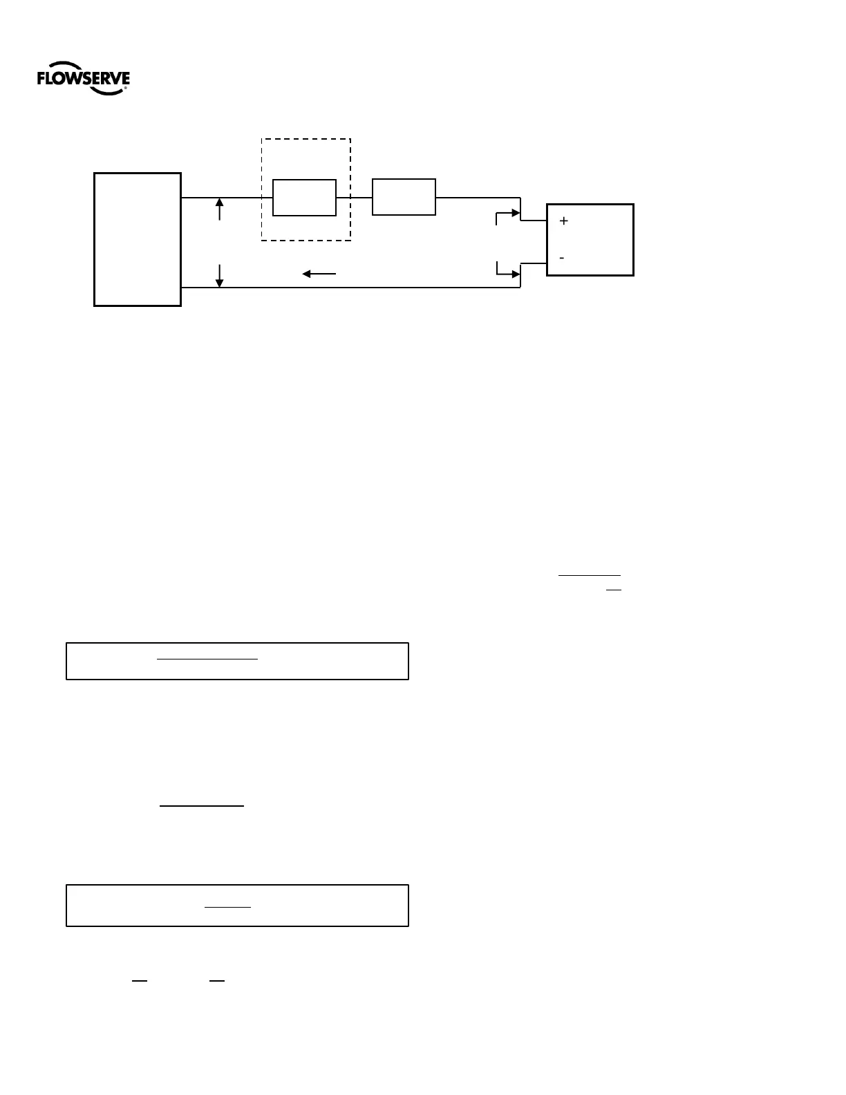
The input loop current signal to the Logix
®
3200MD+ digital
positioner should be in shielded cable. Shields must be tied
to a ground at only one end of the cable to provide a place
for environmental electrical noise to be removed from the
cable. In general, shield wire should be connected at the
source, not at the positioner.
20.2.3 Intrinsically Safe Barriers
When selecting an intrinsically safe barrier, make sure the
barrier is HART compatible. Although the barrier will pass
the loop current and allow normal positioner control, if not
compatible, it may prevent HART communication.
20.2.4 Grounding and Conduit
The grounding terminals, located by the electrical conduit
ports should be used to provide the unit with an adequate
and reliable earth ground reference. This ground should be
tied to the same ground as the electrical conduit.