Logix
®
3200MD+ Digital Positioners FCD LGENIM0110-0 05/16
flowserve.com 17
9 Connect regulated air supply to appropriate port in
manifold. See section 19 TUBING.
10 Connect the power to the 4-20 mA terminals. See
section 20 ELECTRICAL CONNECTIONS.
11 Remove main cover and locate DIP switches and
QUICK-CAL/ACCEPT button.
12 Refer to sticker on main board cover and set DIP
switches accordingly. See section 21 STARTUP.
13 Press the QUICK-CAL/ACCEPT button for three to
four seconds or until the positioner begins to move.
The positioner will now perform a stroke calibration.
14 If the calibration was successful the green LED will
blink GGGG or GGGY and the valve will be in control
mode.
15 If calibration fails, as indicated by a RGGY blink code,
retry the calibration. If it still fails, the feedback values
were exceeded and the arm must be adjusted away
from the positioner’s limits. Rotate the feedback shaft
so that the full free travel of the feedback shaft is in
the range of the actuator movement. Optionally,
continue to attempt the calibration. Each calibration
attempt adjusts the acceptable limits and it should
pass eventually.
CAUTION: Remember to remove the air supply before
re-adjusting take-off arm.
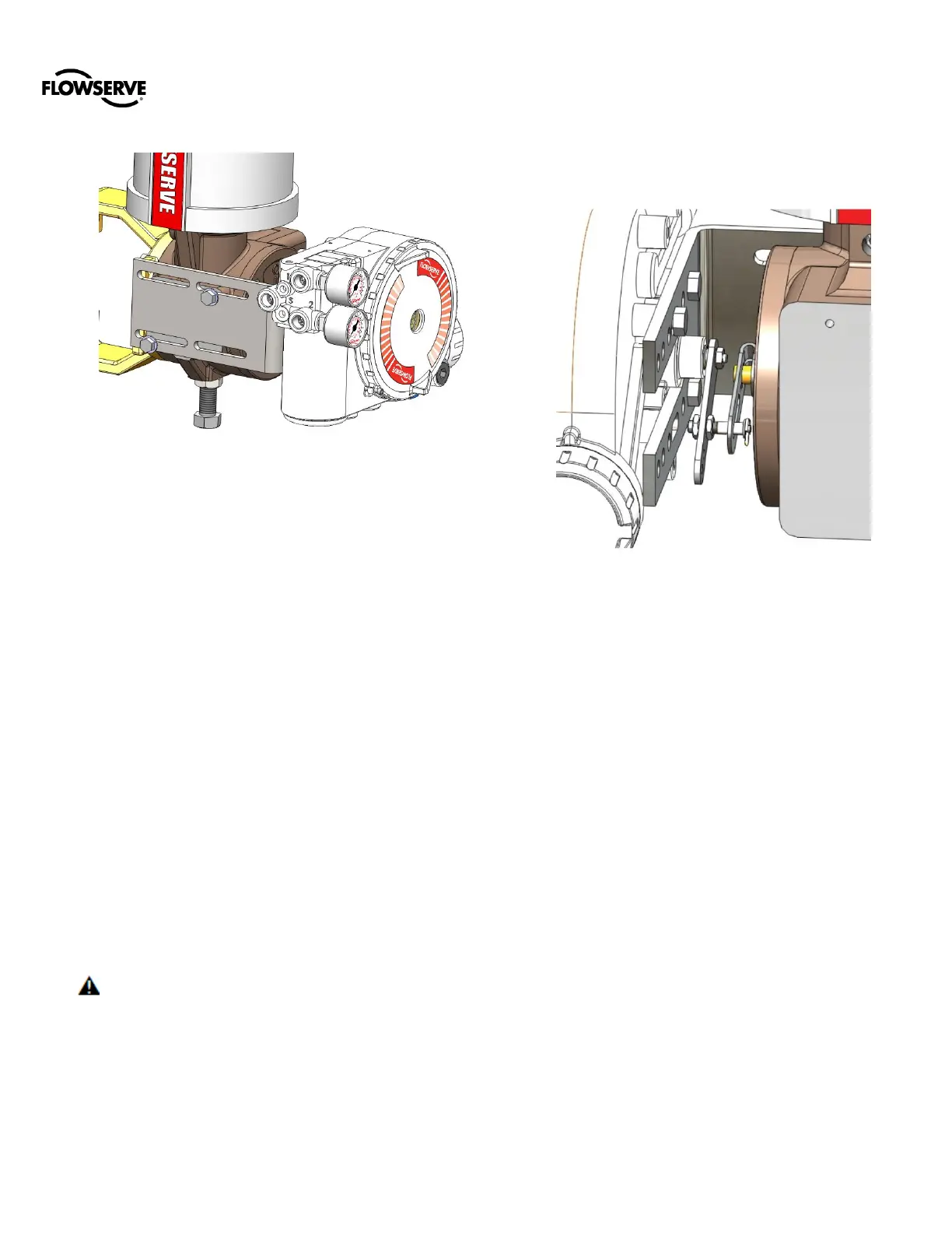
NOTE: If mounted properly, the follower arm should be
horizontal when the valve is at 50% stroke and should
move approximately ±30° from horizontal over the full
stroke of the valve.
NOTE: To virtually eliminate non-linearity, use the
Linearization feature on the Custom Characterization page
of the DTM.