Logix
®
3200MD+ Digital Positioners FCD LGENIM0110-0 05/16
flowserve.com 23
20 ELECTRICAL CONNECTIONS
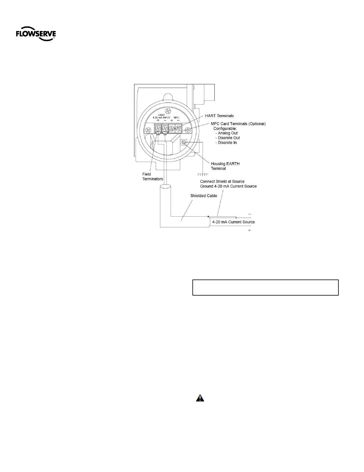
20.1 Electrical Terminals
20.2 Command Input (4-20 mA)
Connection
The Logix
®
3200MD+ is reverse polarity protected,
however, verify polarity when making field termination
connection. Wire 4-20 mA current source to the input
terminal labeled “HART 4-20mA INPUT”. Tighten using 0.5
to 0.6 Nm torque. See Error! Reference source not
found.. Depending on the current source, a HART filter
may be required. See 28.1 Troubleshooting Guide.
20.2.1 Compliance Voltage
Output compliance voltage refers to the voltage limit the
current source can provide. A current loop system consists
of the current source, wiring resistance, barrier resistance
(if present), and the Logix
®
3200MD+ impedance.
The Logix
®
3200MD+ requires that the current loop system
allow for a 10 VDC drop across the positioner at maximum
loop current. The operating current range is from 3.9 to 24
mA.
In order to determine if the loop will support the Logix
®
3200MD+, perform the calculation in the following equation.
The Available Voltage must be greater than 10VDC in
order to support the Logix
®
3200MD+. Also, see Table 1:
Input Signal.
Equation 1
The available voltage (12.5 V) is greater than the required
voltage (10.0 V) therefore; this system will support the
Logix
®
3200MD+. The Logix
®
3200MD+ has an input
resistance equivalent to 500 Ω at a 20 mA input current.
CAUTION: The current must always be limited for 4-
20 mA operation. Never connect a voltage source directly
across the Logix
®
3200MD+ terminals. This could cause
permanent circuit board damage.