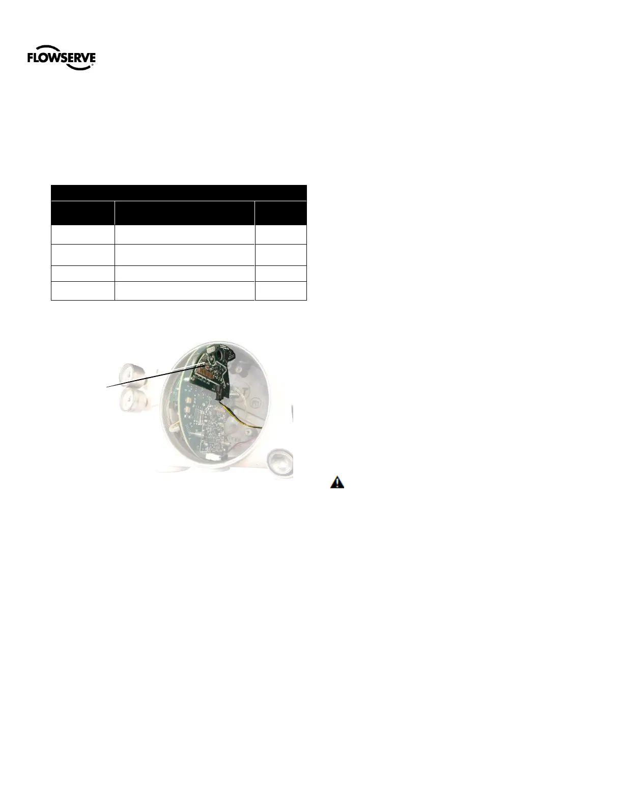
Figure 30: Multi-Function Card
25.1 Analog Output (AO)
Configure the MFC as an Analog Output device to produce
a 4-20 mA signal that corresponds to the position of the
valve.
Output follows actual position of valve, including all failure
modes of positioner except loss of power. An output of <
1.0 mA is transmitted when the positioner loses power.
Calibration of the analog output signal is performed using
the display menu, a HART handheld communicator, or the
ValveSight
®
DTM or push-buttons. To change the Multi-
Function Card to the Analog Output function and calibrate
using the buttons, see section 22.7.
The MFC configured as an AO does not interfere with
positioner operation.
NOTE: The AO signal corresponds with the Signal At
Closed configuration switch setting. If the valve closes
with a 4 mA signal, the AO will show a 4 mA signal when
closed. If the valve closes with a 20 mA signal, the AO will
show a 20 mA signal when closed.
25.2 Discrete Output (DO)
Use the Discrete Output function of the MFC to indicate a
variety of conditions such as alarms, warnings, position
limits, etc. Alarms that are masked will not cause the DO to
trip. The current is normally high, and drops low when one
of the pre-configured states occurs.
Configuration of the discrete output signal is done using the
ValveSight
®
DTM or push-buttons. To change the Multi-
Function Card to the Discrete Output function using the
buttons, see section 22.7.
The MFC configured as a DO does not interfere with
positioner operation.
The MFC DO complies with DIN 19234 standard. For
specific current limits, see Table 12: Auxiliary Card Status.
25.3 Discrete Input (DI)
Use the Discrete Input function of the MFC to signal the
positioner to begin a partial stroke test, or move to a
predefined position as long as the signal remains.
Supply a low voltage (or no voltage) to indicate a normal
state. Raise the voltage to indicate the tripped state.
Configuration of the discrete output signal is done using the
display menu, a HART handheld Communicator, or the
ValveSight
®
DTM.
For specific voltage limits, see Table 12: Auxiliary Card
Status.
CAUTION: During the use of the Discrete Input
function, the valve may stroke unexpectedly. Follow
internal procedures, ensuring that the configured
movement of the valve (performing a PST or moving to a
set-point) is allowed. Notify proper personnel that the valve
will stroke, and make sure the valve is properly isolated if
required.