Logix
®
3200MD+ Digital Positioners FCD LGENIM0110-0 05/16
flowserve.com 11
16 SPECIFICATIONS
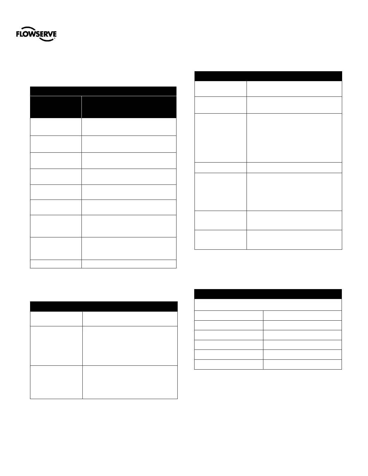
16.1 Input Signal
Positioner Alone
or with
Multi-Function Card
Two-wire, 4-20 mA
10.0 VDC plus line losses.
Minimum Required
Operating Current
Maximum Shut-down
Current
Power Interruption
Time Limit
After power has been applied for at least 10
seconds, a 60 ms power interruption will not
cause the positioner to reset.
Time from application of power to begin
controlling valve < 1.0 second.
Table 2: Pneumatic Output
0 to 100% of air supply pressure.
14.3 Nm³/h @ 1.5 bar
(8.44 SCFM @ 22 PSI)
30.6 Nm³/h @ 4.1 bar
(18.0 SCFM @ 60 PSI)
Primary Output Ports
(Port is pressurized in
energized state. Port
is exhausted upon loss
of power.)
Double Acting Relay – Port 1
The air supply must be free from moisture,
oil and dust by conforming to the ISA
7.0.01 standard. (A dew point at least 18
degrees Fahrenheit below ambient
temperature, particle size below five
microns—one micron recommended—and
oil content not to exceed one part per
million).
Air, sweet natural gas, nitrogen and CO2
are acceptable supply gasses.
Sour natural gas is not acceptable.
For Type nA and Type tb installation only
air or inert gas may be connected to the air
supply inlet.
0.5 Nm³/h @ 4 bar
(0.3 SCFM @ 60 PSI)
12 SCFM @ 60 PSI (0.27 Cv)
16.4 Analog Output – Multi-Function
Card
Table 4: 4 to 20 mA Analog Output Specification
For entity parameters, see section 17 HAZARDOUS AREA
CERTIFICATIONS.
10.0 to 40 VDC, (24 VDC Typical)
-52 to 85°C (-61.6 to 185°F)