Page 36
FW-E115-P-M_v0203_03_EN.docx
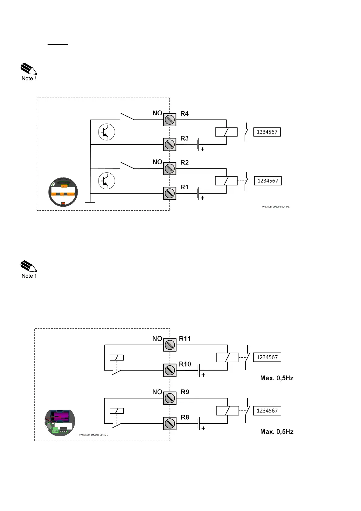
Type OT
Two passive transistor outputs (D1 and D2) are available with a maximum pulse frequency of 500Hz.
Max. driving capacity 300mA@50V DC.
With type OT:
• Terminals R1 and R3 are common ground (GND) terminals.
• When retransmit mode is selected the minimum on and off-time is 50μs.
Fig. 16: Terminal connections – Transistor outputs D1 – D2
Type OR
Two mechanical normally open relay outputs (D5 and D6) are available with a maximum pulse
frequency of 0.5Hz. Max. switch power 240V 0.5A per output.
With type OR:
• Use power supply terminals P5-P6.
• The required supply voltage is 24 - 27V DC!
• Be sure that the output frequency does not exceed 0.5Hz, else the relay life time and
reliability will be reduced significantly.
• The output functionality of digital output D5 and D6 correspond to the functionality of
digital outputs D1 and D2, respectively
• When retransmit mode is selected, the relays are not activated.
Fig. 17: Terminal connections – Mechanical relay outputs D5 – D6

 Loading...