Page 35
FW-E115-P-M_v0203_03_EN.docx
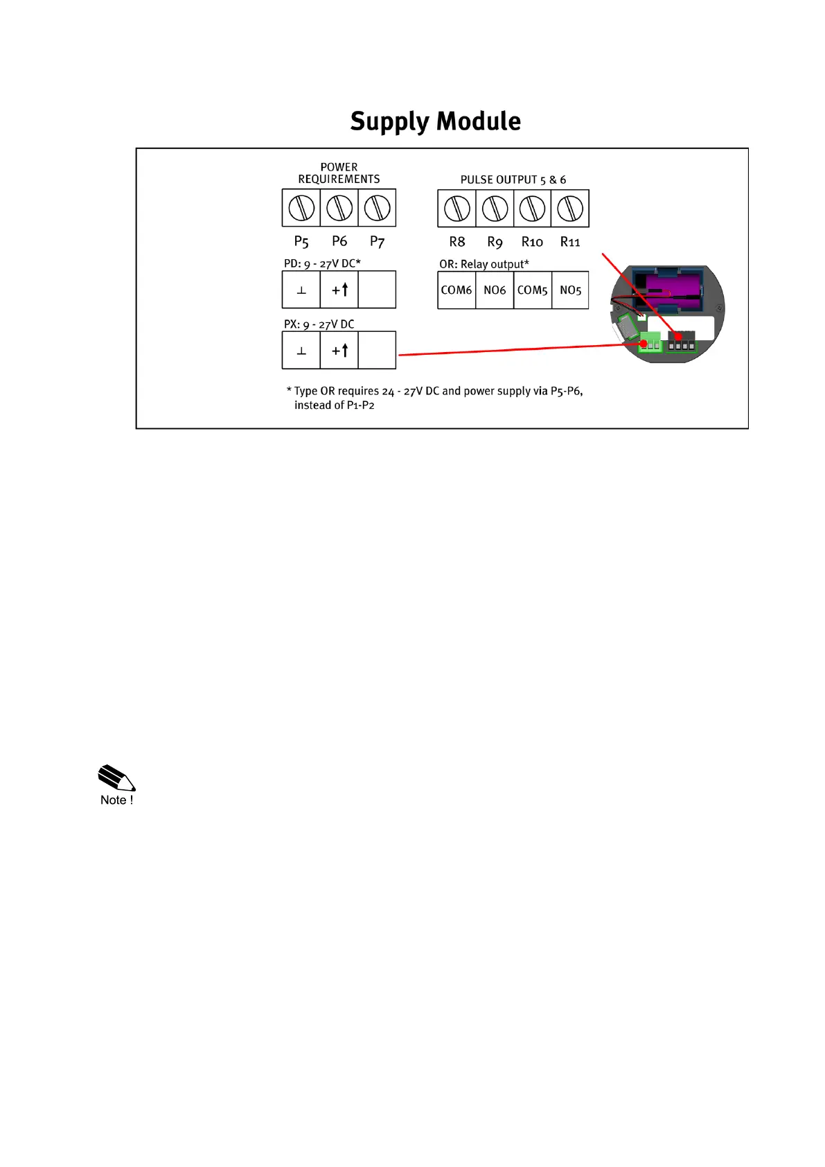
The following terminal connectors are available for the option OR – Mechanical relays (RSM Relay
Supply Module):
Fig. 15: Terminal connectors RSM
4.6 TERMINAL CONNECTIONS
4.6.1 TERMINAL P1-P2 AND P5-P6: POWER SUPPLY – TYPE PD/PX
Connect an external power supply of 9-27VDC to these terminals.
When power is applied to these terminals, discharge of the (optional) internal battery will be
disabled. See also 4.4.2: VOLTAGE SELECTION SENSOR SUPPLY.
Power requirements for sensor supply P3:
• 8.2V sensor supply requires 9-27V;
• 12V sensor supply requires 13-27V;
• 24V = V-input – 1V (max 27V).
4.6.2 TERMINAL R1-R2 / R10-R11; PULSE OUTPUT R1 AND R5
The functionality of the pulse outputs is programmed through the PULSE menu (SETUP-menu 8).
See paragraph 3.3.9 for more details.
• The digital (transistor) outputs D1 and D2 have a maximum frequency of 500Hz.
• Be sure that the output frequency of the optional digital (relay) outputs D5 and D6 do not
exceed 0.5Hz, else the relay life time and reliability will be reduced significantly.
• When retransmit mode is selected in the PULSE MODE menu (SETUP 8.1), only Type
OT outputs D1 and D2 will retransmit the frequency of signal A and B, respectively. In all
other modes, Type OR outputs D5 and D6 will follow output D1 and D2, respectively.

 Loading...