Insulation Tester
Measurements
15
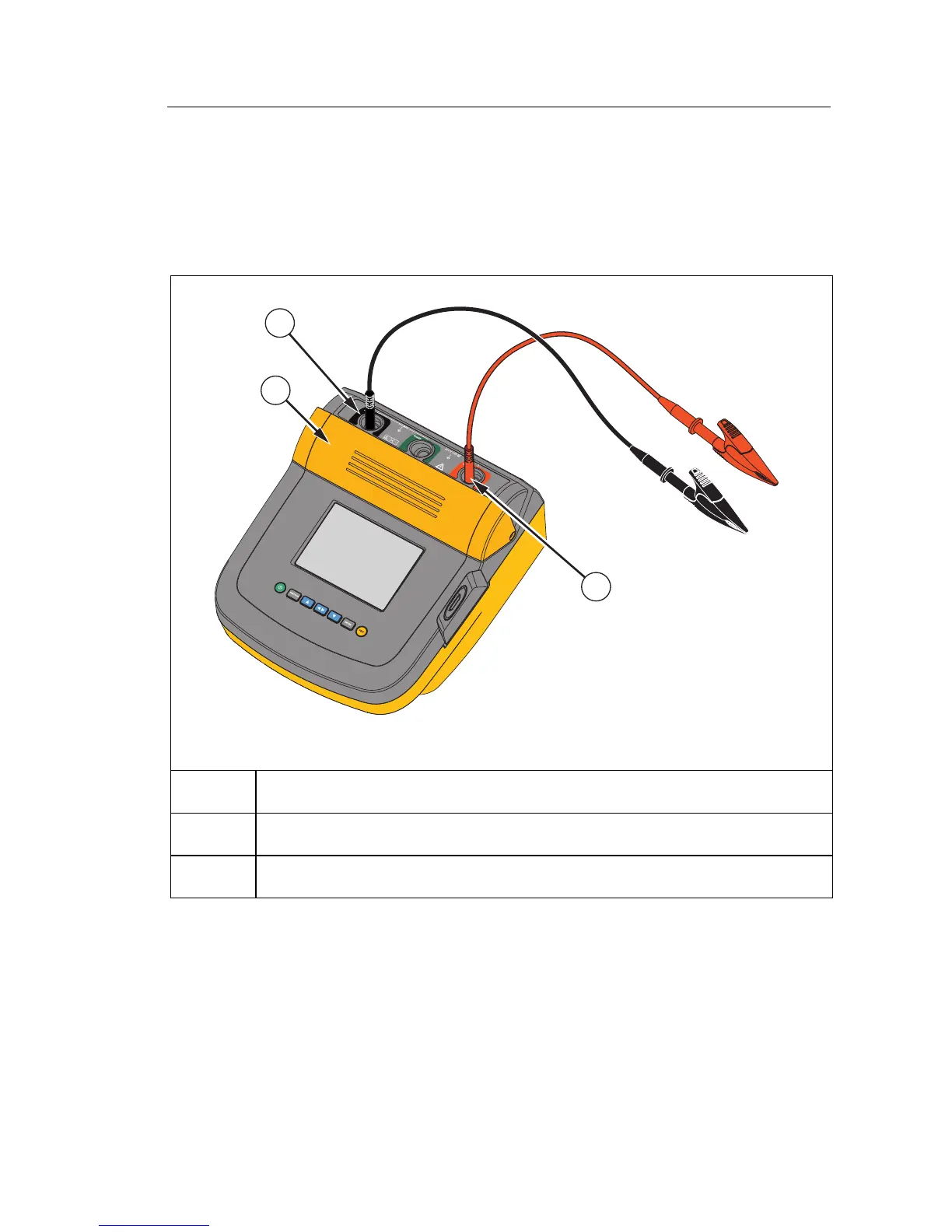
To connect to the circuit under test:
1. Move the safety shutter to access the input terminals.
2. Put the test leads into the correct terminals shown, see Figure 9.
3. Connect the test leads to the circuit under test.
2
3
1
GHH09.EPS
(-) Negative Terminal
(+) Positive Terminal
Safety Shutter
Figure 9. Test Lead Connections
Note
The Tester is NOT specified below 200 k
Ω
. When the leads are
shorted and a test is performed, the Tester gives an unspecified
reading that is greater than zero. This is normal for this Testers input
circuitry configuration and does not change readings that are in the
specified accuracy range.