1652C/1653B/1654B
Users Manual
14
Table 6. Display Features (cont.)
No. Annunciator Meaning
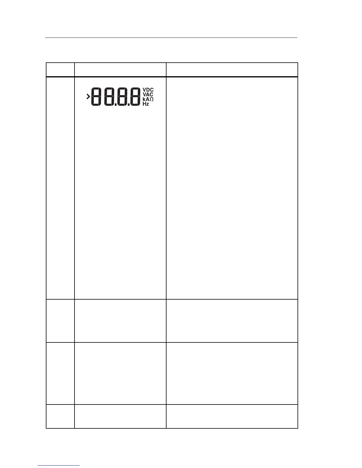
Secondary display and measurement
units. Some tests will return more than
one result or return a computed value
based on the test result. This will occur
with:
• Volts
• Secondary display shows line
frequency.
• Insulation tests
• Secondary display shows actual test
voltage.
• Loop/line impedance
• Secondary display shows PEFC
(Prospective Earth Fault Current) or
R
E
PSC (Prospective Short Circuit
Current).
• RCD switching time
• Secondary display shows U
F
fault
voltage.
• RCD tripping current
• Secondary display shows U
F
fault
voltage.
battery test Appears when you are testing the
batteries. For more information see
“Testing and Replacing the Batteries”
on page 41.
ZERO
Appears when you press the
button to zero the leads. After the
zeroing operation, the icon stays
illuminated indicating that zeroing has
been performed. Only used when
performing continuity or loop testing.
Potential danger. Appears when
measuring or sourcing high voltages.