EasyManuals Logo

Fluke 1652C User Manual

Fluke 1652C
66 pages
To Next Page IconTo Next Page
To Previous Page IconTo Previous Page
Page #21 background imageLoading...
Page #21 background image
Electrical Installation Tester
Operating the Tester
13
Table 6. Display Features (cont.)
No. Annunciator Meaning
Appears when the instrument is
overheated. The Loop test and RCD
functions are inhibited when the
instrument is overheated.
Appears when an error occurs. Testing
is disabled. See “Error Codes” on
page 16 for a listing and explanation of
possible error codes.
Appears when the instrument is
uploading data using Fluke PC
software.
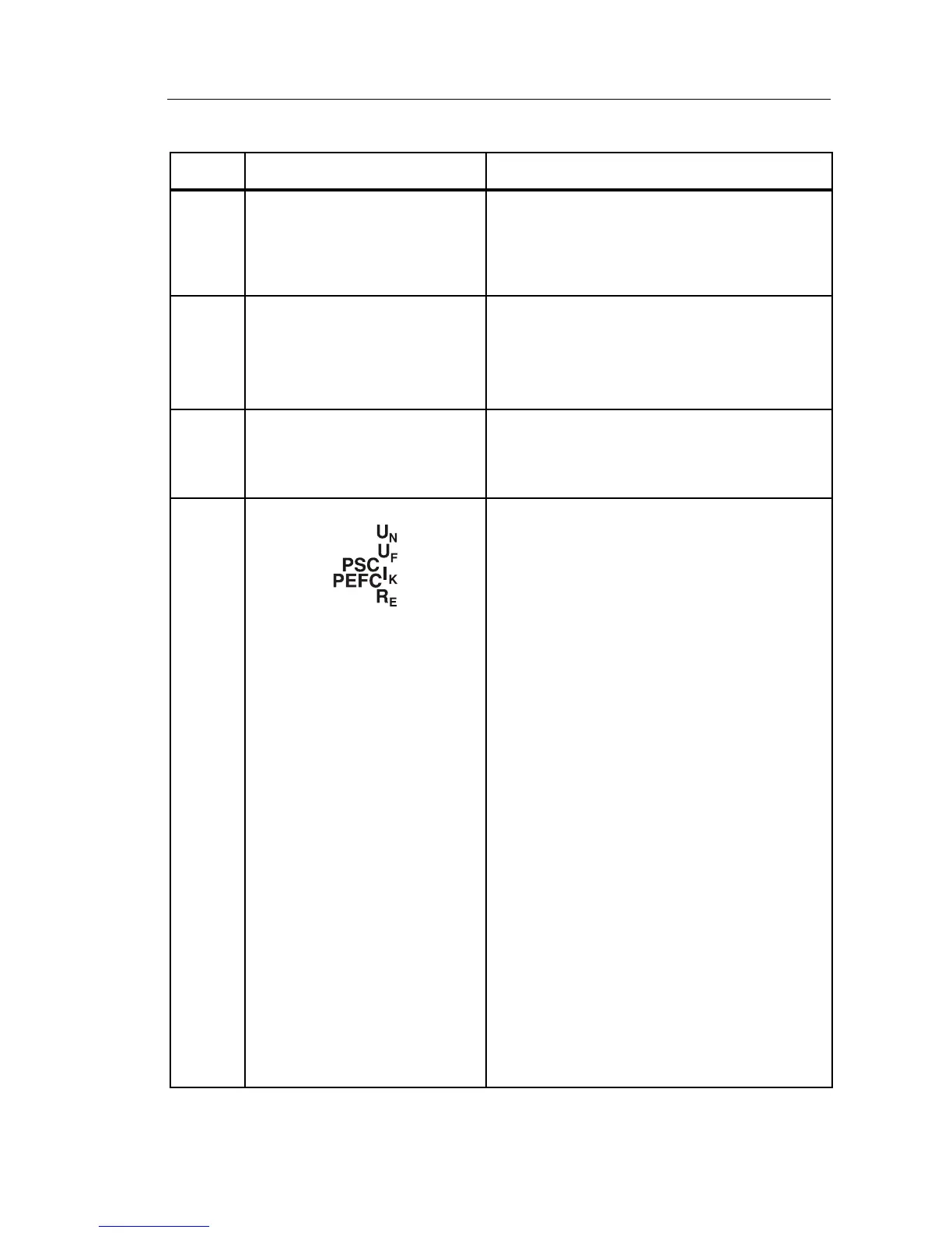
Name of the secondary measurement
function.
U
N
Test voltage for insulation test.
U
F
Fault voltage. Measures neutral to
earth.
PSC
Prospective Short Circuit. Calculated
from measured voltage and impedance
when reading line to neutral.
PEFC
Prospective Earth Fault Current.
Calculated from voltage and loop
impedance which is measured line to
protective earth.
I
K
In combination with the PSC or PEFC
symbol, indicates a short circuit current.
R
E
Earth resistance.

Table of Contents

Other manuals for Fluke 1652C

Questions and Answers:

Question and Answer IconNeed help?

Do you have a question about the Fluke 1652C and is the answer not in the manual?

Fluke 1652C Specifications

General IconGeneral
Test Voltage50 V, 100 V, 250 V, 500 V, 1000 V
Loop and Line Resistance0.01 Ω to 2000 Ω
RCD TestingYes
DisplayDigital
Frequency45 Hz to 65 Hz
Phase Sequence IndicatorYes
Power Supply6 x 1.5 V AA batteries
Weight1.2 kg
Voltage AC500 V
Voltage DC500 V
RCD Trip Current10 mA, 30 mA, 100 mA, 300 mA, 500 mA
RCD Trip Test1x
Safety StandardsEN 61010-1
Operating Temperature-10°C to +50°C
Earth Resistance TestNot available

Related product manuals