Electrical Installation Tester
Specifications
53
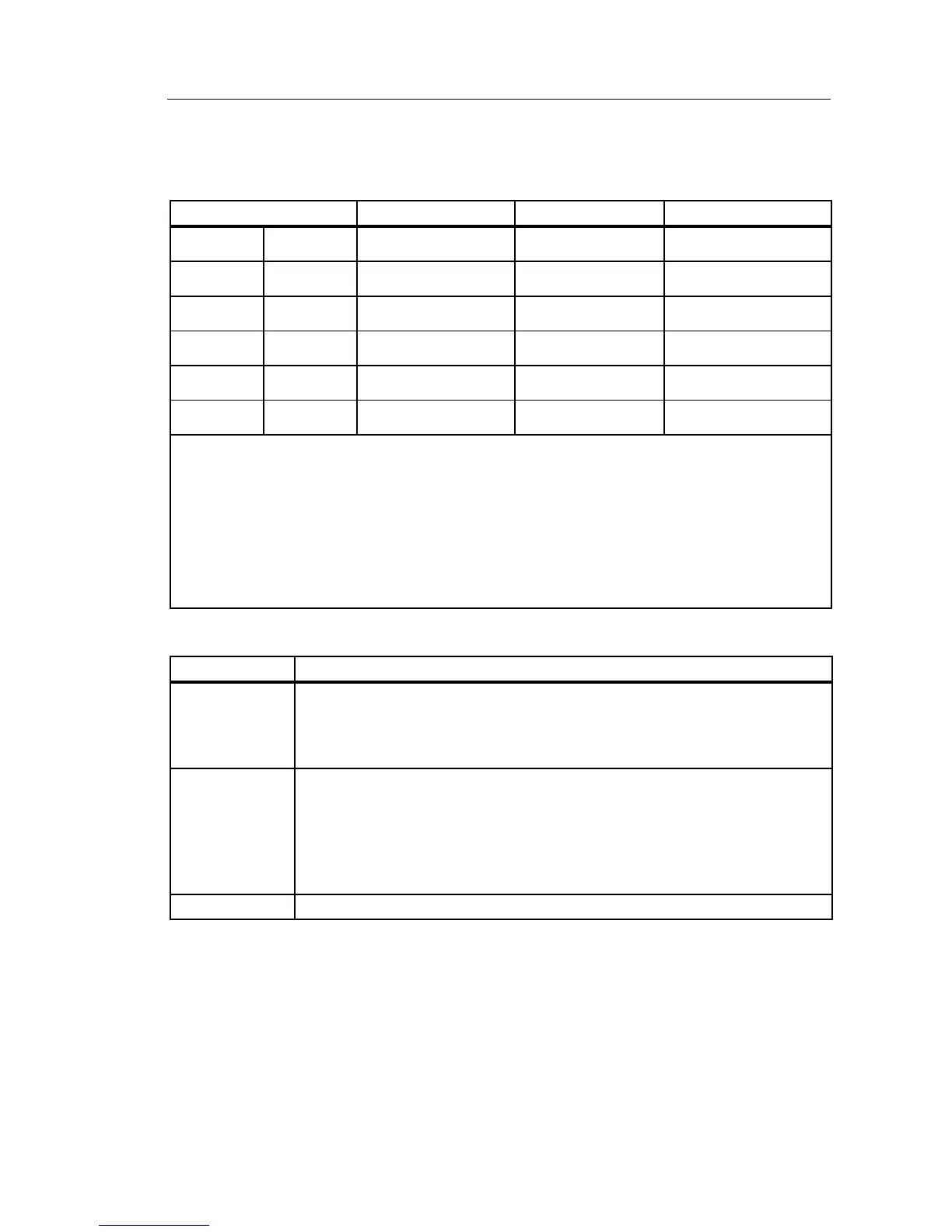
RCD Testing
RCD Types Tested
RCD Type
[6]
Model 1652C Model 1653B Model 1654B
AC
[1]
G
[2]
√ √ √
AC S
[3]
√ √ √
A
[4]
G √ √ √
A S √ √ √
B
[5]
G √
B S √
Notes
[1] AC – Responds to ac
[2] G – General, no delay
[3] S – Time delay
[4] A – Responds to pulsed signal
[5] B – Responds to smooth dc
[6] RCD test inhibited for V >265 ac
RCD tests permitted only if the selected current, multiplied by earthing resistance, is <50 V.
Test Signals
RCD Type Test Signal Description
AC
(sinusoidal)
The waveform is a sinewave starting at zero crossing, polarity
determined by phase selection (0 ° phase starts with low to high zero
crossing, 180 ° phase starts with high to low zero crossing). The
magnitude of the test current is I
Δ
n x Multiplier for all tests.
A
(half wave)
The waveform is a half wave rectified sinewave starting at zero,
polarity determined by phase selection (0 ° phase starts with low to
high zero crossing, 180 ° phase starts with high to low zero crossing).
The magnitude of the test current is 2.0 x I
Δ
n (rms) x Multiplier for all
tests for I
Δ
n = 0.01A. The magnitude of the test current is 1.4 x I
Δ
n
(rms) x Multiplier for all tests for all other I
Δ
n ratings.
B (DC) This is a smooth DC current according to EN61557-6 Annex A