1652C/1653B/1654B
Users Manual
32
Measuring RCD Tripping Current
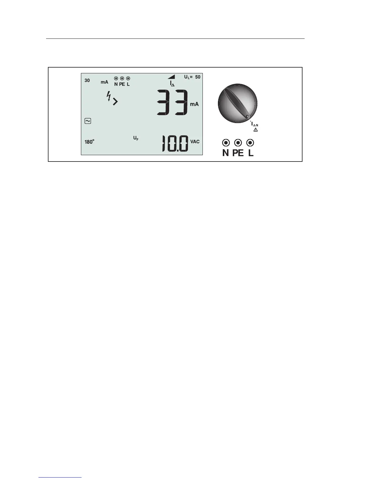
apx009f.eps
Figure 17. RCD Tripping Current/Switch and Terminal Settings
This test measures the RCD tripping current by applying a test current and then
gradually increasing the current until the RCD trips. You can use the test leads
or mains cord for this test. A 3-wire connection is required.
Warning
• Test the connection between the N-conductor and earth
before starting the test. A voltage between the N-conductor
and earth may influence the test.
• Leakage currents in the circuit following the residual current
protection device may influence measurements.
• The displayed fault voltage relates to the rated residual
current of the RCD.
• Potential fields of other earthing installations may influence
the measurement.
Note
If the L and N terminals are reversed, the tester will auto-swap them
internally and continue testing. If the tester is configured for UK
operation, testing will halt and you will need to determine why the L
and N are swapped. This condition is indicated by arrows above or
below the terminal indicator symbol ().
Type A and type B RCDs do not have the 1000 mA option available.
To measure RCD tripping current:
1. Turn the rotary switch to the I
ΔN
position.
2. Press to select the RCD current rating (10, 30, 100, 300, or 500 mA). If
the RCD has a special nominal current setting other than the standard