EasyManuals Logo

Fluke 1652C User Manual

Fluke 1652C
66 pages
To Next Page IconTo Next Page
To Previous Page IconTo Previous Page
Page #42 background imageLoading...
Page #42 background image
1652C/1653B/1654B
Users Manual
34
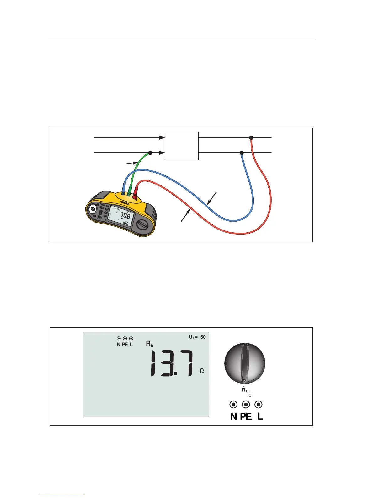
RCD Testing in IT Systems
RCD testing at locations with IT systems requires a special test procedure
because the Protective Earth connection is grounded locally and is not tied
directly to the power system.
The test is conducted at the electrical panel using probes. Use the connection
shown in Figure 18 when performing RCD testing on IT electrical systems.
RCD
Mains Supply
PE (L2/Green)
L (L1/Red)
N (L3/Blue)
apx023f.eps
Figure 18. Connection for RCD Testing on IT Electrical Systems
The test current flows through the upper side of the RCD, into the L terminal,
and returns though the PE terminal.
Measuring Earth Resistance
(Model 1653B and 1654B Only)
apx010f.eps
Figure 19. Earth Resistance Display/Switch and Terminal Settings

Table of Contents

Other manuals for Fluke 1652C

Questions and Answers:

Question and Answer IconNeed help?

Do you have a question about the Fluke 1652C and is the answer not in the manual?

Fluke 1652C Specifications

General IconGeneral
Test Voltage50 V, 100 V, 250 V, 500 V, 1000 V
Loop and Line Resistance0.01 Ω to 2000 Ω
RCD TestingYes
DisplayDigital
Frequency45 Hz to 65 Hz
Phase Sequence IndicatorYes
Power Supply6 x 1.5 V AA batteries
Weight1.2 kg
Voltage AC500 V
Voltage DC500 V
RCD Trip Current10 mA, 30 mA, 100 mA, 300 mA, 500 mA
RCD Trip Test1x
Safety StandardsEN 61010-1
Operating Temperature-10°C to +50°C
Earth Resistance TestNot available

Related product manuals