Electrical Installation Tester
Making Measurements
29
• Potential fields of other earthing installations may influence
the measurement.
• Equipment (motors, capacitors) connected downstream of
the RCD may cause considerable extension of the tripping
time.
Note
If the L and N terminals are reversed, the tester will auto-swap them
internally and continue testing. If the tester is configured for UK
operation, testing will halt and you will need to determine why the L
and N are swapped. This condition is indicated by arrows above or
below the terminal indicator symbol ().
Type A and type B RCDs do not have the 1000 mA option available.
To measure RCD tripping time:
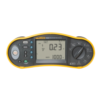
1. Turn the rotary switch to the ΔT position.
2. Press to select the RCD current rating (10, 30, 100, 300, 500, or
1000 mA).
3. Press to select a test current multiplier (x ½, x 1, x 5, or Auto). Normally
you will use x 1 for this test.
4. Press to select the RCD test-current waveform:
• – AC current to test type AC (standard AC RCD) and type A
(pulse-DC sensitive RCD)
• – Half-wave current to test type A (pulse-DC sensitive RCD)
• – Delayed response to test S-type AC (time delayed AC RCD)
• – Delayed response to S-type A (time delayed pulse-DC
sensitive RCD)
• – Smooth-DC current to test type B RCD
• – Delayed response to S-type B (time delayed smooth-DC
current RCD)
5. Press to select the test current phase, 0° or 180°. RCDs should be
tested with both phase settings, as their response time can vary
significantly depending on the phase.
Note
For RCD type B () or S-type B ( ), you must test with both
phase settings.