Fluke 190 Series II
Users Manual
100
A message appears asking you whether to start the 10:1
probe calibration.
6
F4
Start the probe calibration.
A message appears telling you how to connect the probe.
Connect the red 10:1 voltage probe to input A and to the
probe calibration reference signal as shown in Figure 51.
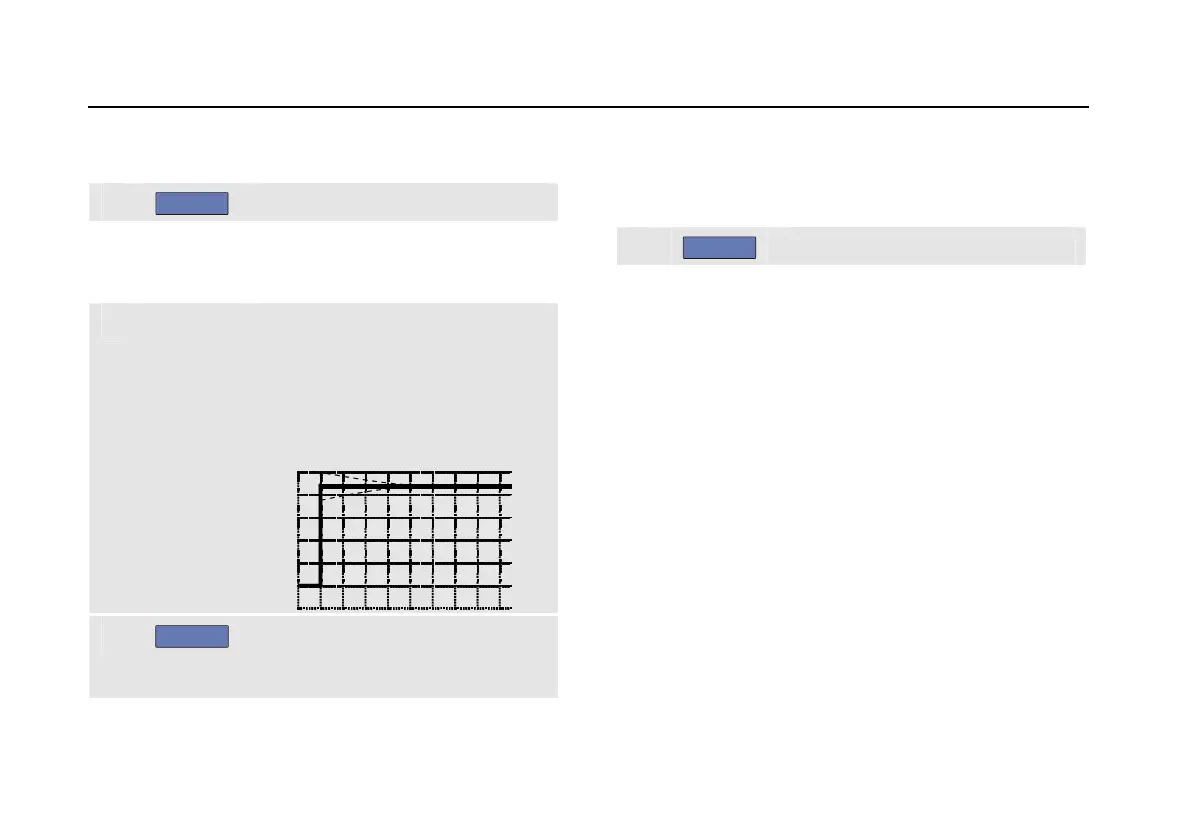
7
Adjust the trimmer screw in the
probe housing until a pure square
wave is displayed.
For instructions to access the
trimmer screw in the probe housing
see the probe instruction sheet.
8
F4
Continue with DC calibration.
Automatic DC calibration is only
possible for 10:1 voltage probes.
The test tool automatically calibrates itself to the probe.
During calibration you should not touch the probe. A
message indicates when the DC calibration has completed
successfully.
9
F4
Return.
Repeat the procedure for the blue 10:1 voltage probe on
input B, the gray 10:1 voltage probe on input C and the
green 10:1 voltage probe on input D.
Note
When using 100:1 voltage probes, choose 100:1
attenuation to perform an adjustment.

 Loading...